GPUSmith Article
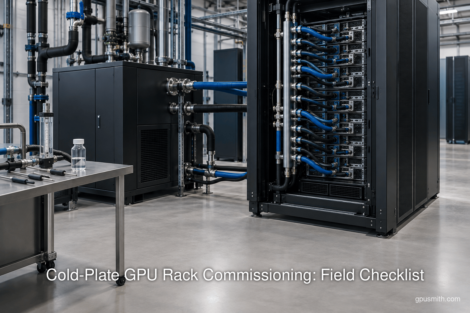
Cold-Plate GPU Rack Commissioning: Field Checklist
Summary
- 01Release a cold-plate GPU rack only after its configuration-specific acceptance basis, mechanical integrity, cleanliness, fluid quality, controls, leak response and staged heat removal are supported by field evidence.
- 02Keep the Technology Cooling System and Facility Water System boundaries distinct, with separate acceptance records and tagged measurements at the points that can fail independently.
- 03Use the purchased equipment's approved limits for pressure, temperature, flow, chemistry and redundancy; published examples are not universal acceptance values.
- 04Reconcile liquid heat pickup with metered IT power using the actual fluid properties, synchronized measurements and a documented uncertainty interval.
- 05Turn over a reproducible operating baseline containing raw trends, calibration and sample records, test results, deviations, corrective actions and signed retests.
Inside this article
- 01Executive Summary
- 02Introduction and Background
- 03Define the Loop and Freeze the Acceptance Basis
- 04Mechanical Completion, Flush, Fill and Circulation
- 05Water Chemistry and Filtration Acceptance
- 06Functional Tests and Leak Response
- 07Data Analysis and Evidence
- 08Turnover Pack, Monitoring and Retest Triggers
- 09Implications and Future Directions
- 10Conclusion
Executive Summary
A cold-plate GPU rack is ready for information technology (IT) load only when the installed loop has passed a documented sequence: reconcile the design and vendor submittals; prove mechanical integrity and cleanliness; fill, vent and circulate the approved fluid; establish water-quality and instrument baselines; test controls and leak response; then reconcile heat removal at staged load. The Technology Cooling System (TCS) is the secondary loop between the coolant distribution unit (CDU) and rack equipment; the Facility Water System (FWS) is a separate facility-side circuit. The two circuits need separate acceptance records. [1] This report is a field pack, not a universal set of rack limits: manufacturers provide configuration-specific flow and pressure requirements, and the CDU approach temperature affects the temperature delivered to IT. [2] [3]
The controlling document set should name the purchased server, cold plate, quick disconnect (QD), manifold, CDU and fluid, plus the approved treatment plan and owner acceptance schedule. As of September 2026, OCP lists Revision 2 of its cold-plate cooling-loop requirements. Its water-based fluid guideline explicitly requires project customization. [4] [5] For one applicable water-based startup procedure, OCP recommends sidestream filtration finer than 5 micrometers and sampling weekly for one month, monthly for a quarter and quarterly thereafter. Those are guideline examples, not automatic warranty conditions for a different fluid or purchased rack. [6] [7]
The acceptance sheet should capture calibrated supply and return temperatures, flow, differential pressure, filter differential pressure, fluid inventory, laboratory results, alarm states, event timestamps and the location of every leak sensor. During a controlled load ramp, calculate liquid heat pickup as Q = mass flow × specific heat × temperature rise, using the actual fluid mixture and measured points. Compare it with metered IT power as a reconciliation, with uncertainty and air-cooled loads recorded separately; nameplate power is not actual operating power. [8] [9] NIST’s uncertainty guidance calls for all significant contributors in the measurement model. [10]
Turnover is the transfer of a usable operating baseline, not merely an assertion that the rack ran. Preserve raw trends, calibration records, sample reports, test methods, setpoints, alarm cause and effect, corrective actions and signed retests. ASHRAE’s commissioning framework emphasizes recording acceptable performance during functional and integrated tests. [11] An adjacent engineering advisor such as GPU Smith describes acceptance against written criteria and an as-built documentation set; for this topic, that perspective belongs in the acceptance process, not in a vendor comparison. [12]
Introduction and Background
Direct liquid cooling moves part of a GPU server’s heat into a circulating liquid through cold plates. Commissioning starts after physical installation and ends only when the owner can operate the specific rack and its connected infrastructure within approved limits. This article addresses the field question: what evidence proves a cold-plate GPU rack, CDU and TCS loop are ready for IT load? The answer is a sequence of hold points and records. A clean pipe alone does not prove flow at the remote chassis; a running pump does not prove that a leak event reaches the correct operator; and a nominal CDU rating does not prove performance at the project’s hydraulic duty point.
The system boundary matters because a CDU separates circuits with different water-quality duties. ASHRAE notes that TCS quality requirements are more stringent than FWS requirements. [13] The CDU’s actual location and the vendor’s scope must be shown on the as-built diagram so that the installer’s and operator’s responsibilities are clear. At each boundary, assign a named party to submit the design value, verify the as-built installation, perform the test and accept the result. No generic pressure, temperature, flow, chemistry or redundancy number in this report substitutes for the purchased equipment’s approved limit.
The working set should include signed piping and instrumentation diagrams, hydraulic calculations, CDU pump and heat-exchanger data, server and cold-plate submittals, QD and hose drawings, fluid safety and compatibility information, a treatment plan, point list, alarm cause-and-effect schedule and test forms. The owner should make commissioning and maintenance responsibilities explicit in that set. The result is a traceable path from design intent to field evidence. GPU Smith’s public scope includes a power, space, cooling and network requirement schedule, a useful example of how an adjacent advisor can frame owner-side requirements without being a CDU manufacturer. [14]
Define the Loop and Freeze the Acceptance Basis
Draw the physical and control boundaries
Trace the supply and return from the FWS connection through the CDU heat exchanger, TCS pump, filters, fill and drain points, branches, manifolds, hoses, QDs and cold plates, then back to the CDU. Mark sample taps and isolation valves on the drawing. OCP describes the transfer fluid in the closed secondary loop, while ASHRAE distinguishes the quality requirements for TCS and FWS. [1] [13] Where a skid or in-rack CDU has multiple loops, label each circuit separately. Give every sensor and valve a unique tag that matches the controls list and trend export.
The rack manifold distributes coolant within the rack. A QD adds a service interface with its own seal material, pressure drop, inclusion and spillage characteristics. The purchased QD specification must establish its air inclusion and spillage behavior; a generic coupling description does not establish an allowable spill volume for a particular rack. The approved QD datasheet must supply the project’s connection orientation, pressure rating, compatible fluid and seal, expected mating life and service procedure. Parker explicitly identifies seal materials matched to temperature and fluids. [15]
Reconcile design with the installed equipment
Start with the approved schedules and compare each tag, serial number and firmware or controller configuration with the installed unit. Verify the CDU’s selected pressure-flow (PQ) curve at the specified fluid concentration and operating temperature. Sum the branch, hose, QD, cold-plate, manifold and filter pressure drops at design flow; the clean-filter value and an allowed loaded-filter condition must both fit the pump’s usable curve. ASHRAE cautions that loaded filter pressure drop can be significantly higher than clean-filter drop. [16] Schneider Electric also notes that component losses sum to the TCS total pressure drop. [17] Do not extrapolate a vendor curve beyond its published range.
Table 1 is the core requirements traceability form. Duplicate its rows for every branch and operating mode. The blank entries are intentional because a purchased system, rather than a generic guide, sets acceptance limits.
| Parameter and unit | Design or OEM basis | Field test and instrument | Result and evidence | Disposition |
|---|---|---|---|---|
| TCS supply and return temperature, °C | Approved server and CDU limits; account for CDU approach [3] | Calibrated paired temperature points at CDU and rack | Trend file, time range, sensor IDs | Pass, retest or approved deviation |
| TCS flow and pressure, L/min and kPa | Server minimum/maximum, CDU PQ curve [2] | Flow meter and supply/return pressure at each critical branch | Raw trace and calculated duty point | Compare at each staged load |
| Filter differential pressure, kPa | Clean and loaded filter values from approved submittal | Upstream/downstream transmitters or calibrated gauge | Baseline and changeout threshold | Record filter model and condition |
| QD and hose integrity | Purchased assembly pressure and service requirements [15] | Approved visual and leak-check method | Certificate, inspection sheet, photos | Defect or retest record |
| Fluid quality and inventory | OEM limits plus approved treatment plan | Sample port, laboratory methods, measured fill volume | Certificate, sample ID, volume sheet | Owner and treatment supplier sign-off |
| Alarm and isolation | Approved point list and cause/effect [18] | Simulated input under OEM-approved method | Event log, timestamps, reset proof | Integrated acceptance |
A row passes only when its measured result and its supporting file are present. A blank design value is an open submittal issue, not a passing test. The CDU capacity, pump margin and available heat exchanger approach should be checked at the specified FWS conditions and with actual filters installed; Schneider Electric recommends acceptance testing under project conditions. [19]
- The TCS is the secondary loop between the CDU and rack equipment.
- Its water-quality requirements are more stringent than those for the FWS.
- The FWS is a separate facility-side circuit, with its own acceptance record.
- Identify facility supply and return conditions when checking CDU duty.
The CDU separates circuits with different water-quality duties; keep their boundaries and acceptance records clear.
A clean pipe alone does not prove flow at the remote chassis; a running pump does not prove that a leak event reaches the correct operator; and a nominal CDU rating does not prove performance at the project’s hydraulic duty point.
Mechanical Completion, Flush, Fill and Circulation
- 01Freeze the basis
Reconcile purchased equipment and vendor submittals, then establish the approved acceptance basis.
- 02Prove integrity and cleanliness
Document the approved pressure or leak check and protect cold plates during the initial flush.
- 03Fill, vent and circulate
Use the approved fluid, vent high points and record stable operating measurements.
- 04Test controls and alarms
Run approved simulations and capture the event path, response and reset evidence.
- 05Reconcile staged load
Compare liquid heat pickup with metered IT power and report measurement uncertainty.
Pre-fill hold point
Before putting liquid into the rack, walk the route against the as-built drawing. Verify support, isolation and drain access, hose labels, QD engagement, vent location, sample ports, sensor placement, filter element and differential-pressure taps. A current Vertiv CDU commissioning guide explicitly checks flushed hoses, pressure-test certification for new pipework, and a vent at the secondary circuit’s highest point. [20] [21] [22] These are examples of vendor requirements for that CDU, not a license to borrow its pressure or hold time for another assembly.
- Integrity file: Collect component certificates, approved leak-test medium and method, test boundary, instrument ID, calibration date, pressure trace and sign-off. Distinguish factory-tested sealed equipment from field joints; Lenovo describes factory gas pressure testing of water-cooled nodes, while field connections still need the purchased system’s site procedure. [23]
- Cleanliness file: Record temporary strainers, bypasses, flushing direction, filter changes, debris observations and final sample. OCP’s water-based startup keeps cold plates isolated during the first flush to avoid exposing them to piping debris. [24]
- Fluid file: Match delivered product and concentration to the approved wetted-material list, fill procedure and supplier documentation. Lenovo’s RM100 instructions call for a rinse before final fill with a fluid containing its required inhibitor and biocide concentrations. [25] [26]
- Control file: Check electrical feeds, protective devices, rotation indication, network links and controller settings against approved drawings before the CDU runs. Vertiv specifically instructs a configuration check before operation. [27]
A pressure or leak check should use the OEM-approved boundary, medium, pressure, duration and isolation method. The record should say whether cold plates, sensors or QDs were included. Do not invent a generic pneumatic test or use a destructive leak demonstration. For example, Dell’s IR7000 procedure calls for low-pressure pump operation and visual checking in its own hose service sequence. [28] That does not establish a universal pressure-test setpoint.
Fill, vent and stabilize
Fill from the prescribed point with the approved fluid, record the volume added and track temporary losses. Vent at high points and at prescribed manifold or chassis locations while observing pressure and reservoir level. In the CDU 100 example, Vertiv directs reduced pump speed after initial fill to remove air; Dell describes a coolant-appearance check at its manifold valve. [29] [30] Once the loop is stable, log supply and return temperature, flow, pressure, filter differential pressure, pump speed, tank level and make-up volume at a defined sampling interval. Record any drift after air purges and after each newly connected dry chassis.
A cold plate leak test procedure is complete only if it defines test limits, connection inspection, detection coverage, response, cleanup and retest evidence. The technician should inspect each service connection, use the OEM’s engagement check, and preserve the leak-check record. Dell’s connector procedure includes a physical engagement check for its QD assembly. [31] The acceptance sheet should distinguish a dry static inspection, a circulation check and a load condition because they stress different joints and operating points.
Water Chemistry and Filtration Acceptance
Water quality is a lifecycle control, not a one-time fill certificate. The OCP guideline addresses a water-based closed TCS loop and says each project must customize it. [5] Confirm that the fluid, additives, wetted metals, polymers, seals and filter media are compatible with one another and with the temperature range. A Certificate of Analysis (COA) for supplied concentrate does not necessarily certify a final mixture prepared on site, so retain the batch COA, mixing record and an analyzed post-fill sample. [32] Document the supplier-approved sampling method and who can adjust the fluid.
Table 2 is a chemistry baseline and monitoring register. It contains measurement categories and methods, while the limit cells must be populated from the approved treatment plan and OEM documents. Different instruments or labs can disagree at low concentrations; record the method, sample location, bottle, preservation and chain of custody before comparing results.
| Parameter | Method and record | Project limit and owner | When to check |
|---|---|---|---|
| Total suspended solids (TSS) and total dissolved solids (TDS) | Laboratory gravimetric method; ASTM D5907 covers dissolved and suspended matter [33] | Supplier/OEM limits; treatment specialist signs | Baseline, after intervention, scheduled samples |
| Conductivity and pH | Calibrated field meter and lab confirmation; ASTM D1125 covers conductivity [34] and ISO 10523 covers pH [35] | Temperature-compensated limits and owner | Fill baseline and trend schedule |
| Hardness and turbidity | Approved laboratory method and field turbidity trend | Project plan; fluid supplier | Fill baseline and upset investigation |
| Microbial count and biocide | Lab culture or approved alternative; inhibitor and biocide concentration | Treatment plan and material compatibility | Baseline and scheduled monitoring [36] |
| Corrosion ions, metals and inhibitor | Approved ion or metals method; EPA lists analytical methods for metals [37] | OEM/treatment supplier target and action band | Baseline, change of fluid or component |
| Filter differential pressure and particulate trend | Installed gauges plus sampled debris; compare clean and loaded conditions [16] | Filter changeout limit and operations owner | Continuous trend and each inspection |
This table deliberately avoids universal chemistry thresholds. A Lenovo water-cooling standard calls for an inline 50-micrometer filter in its own system, while OCP’s water-based guidance recommends a sidestream filter finer than 5 micrometers for its described loop. [38] [6] Those are different positions and functions, so they should not be substituted for each other. Eaton documents 0.2-micrometer sidestream filtration on a named CDU product, another product-specific example. [39] Select the final element, flow fraction, bypass arrangement and changeout trigger from the purchased system and its fluid supplier; record both clean and loaded pressure loss.
OCP suggests a startup sampling cadence of weekly for a month, monthly for a quarter and quarterly thereafter, while ASHRAE warns that a single universal maintenance frequency is impractical. [7] Set the operating schedule using the treatment plan, trend stability and OEM terms. Measure loop volume before dosing: OCP specifically says system volume must be known before additions. [40] The dose worksheet should show measured volume, product concentration, target change, supplier calculation, amount added, mixing time, post-dose sample and authorization. Retain the fluid identity, source, analyses, adjustments and component replacement history for the fluid’s lifetime.
Functional Tests and Leak Response
Functional testing should begin with harmless, approved simulations and proceed through the cause-and-effect schedule signed by the owner and OEM. ASHRAE places full functional testing at Level 4 and integrated testing at Level 5 in its data-center framework. [41] The test team should define prerequisites, expected annunciation, safe state, manual response, restoration and evidence for each input. Where a test could interrupt a running rack, perform it with an approved simulator, maintenance bypass or staged equipment state. The goal is to verify a specified function, not to damage hardware.
- Pump and controls: Check command and feedback, rotation, speed modulation, lead/lag or standby transfer if furnished, and response to a sensor fault. Capture flow and pressure before, during and after the transition.
- Hydraulic alarms: Simulate loss of flow, abnormal differential pressure and high temperature within the controller’s approved test method; verify that values, units, timestamps and alarm routing agree across local panel and building management system (BMS).
- Leak network: Confirm that installed detection at the CDU, rack, chassis, drip tray and high-risk QDs maps to the correct rack. HPE says its direct-liquid-cooled racks include multiple leak-detection points, and NVIDIA describes separate tray and BMS sensor paths in its architecture. [42] [43]
- Isolation: Check the exact configured sequence of notification, controlled de-energization, fluid isolation, reset permission and recommissioning. NVIDIA’s integration documentation expects the BMS to perform liquid or electrical isolation requests, while Vertiv offers configurable alarm-only or shutdown-plus-alarm behavior on its CDU 100. [18] [44]
- Identification: Verify that rack and sensor IDs in the BMS, cluster manager and trend files refer to the same physical equipment. NVIDIA’s Mission Control guidance calls for coordinated rack identifiers. [45]
Table 3 turns the approved cause-and-effect drawing into a field record. The actual response must come from the purchased system’s approved sequence, particularly for energized equipment. For each row, record the injected input, event log, time to indication, operator notification, final valve and power state, reset authority and retest.
| Detection point or input | Expected notification | Approved action to verify | Evidence and reset |
|---|---|---|---|
| CDU drip tray or leak tape | Local controller and BMS alarm | Configured alarm or shutdown mode [44] | Input simulation, event trace, dry reset |
| Rack/manifold leak sensor | Rack-specific BMS and cluster alert | Approved liquid/electrical isolation request [46] | Valve and breaker status, owner release |
| Chassis or tray sensor | Correct chassis/rack identity | Vendor-defined IT protection sequence [43] | Controller log and re-enable approval |
| Low flow or high differential pressure | Tagged point and operator alarm | Pump, bypass or IT response per approved cause/effect [47] | Trend before/after, sensor plausibility |
| High TCS supply temperature | CDU and facility alarm | Vendor-approved load or valve response | Temperature trend, restored setpoint |
The matrix is not complete until a human operator knows the notification route and the reset criteria. A leak event may require physical inspection, cleanup, fluid-quality recheck and a repeat circulation test before IT is re-energized. If redundant pumps, feeds or valves were purchased, record a controlled single-component transfer test; if they were not, mark the row not applicable rather than implying redundancy. A vendor’s startup service description includes leak-tape functionality checks, which is a reminder to test the installed alarm chain rather than merely note sensor presence. [48]
Data Analysis and Evidence
CDU duty-point worksheet
The hydraulic calculation should use the vendor’s PQ curve and the actual as-built pressure-drop schedule. ASHRAE says manufacturers provide configuration-specific flow and pressure data. [2] For each mode, enter TCS fluid identity and temperature, required branch flows, total design flow, return temperature, filter state, FWS supply and return conditions, CDU approach and maximum permitted component pressures. Add pressure losses for all series components and solve the curve intersection. The result is a duty point, not a restatement of nameplate capacity. If the predicted intersection lies outside the published curve, obtain vendor data rather than extrapolating.
A useful worksheet has columns for design, factory witness, field no-load and field staged-load values. It should also identify sensor location: a CDU discharge pressure is not a cold-plate differential pressure, and a facility-side temperature is not a TCS supply temperature. At each stage, capture the measured operating point and compare it with the allowable envelope. Document whether filters were clean, loaded or temporarily bypassed. Schneider Electric cautions that removing a filter can make a CDU rating appear more favorable, so a field comparison needs the installed filter configuration. [17]
Heat balance, uncertainty and load ramp
For a single-phase loop, use Q = m-dot × c_p × ΔT, where Q is liquid heat pickup, m-dot is measured mass flow, c_p is the actual fluid’s specific heat at operating concentration and temperature, and ΔT is measured return minus supply temperature. DOE’s heat-exchanger handbook identifies mass flow, specific heat and coolant temperature change as the inputs. [8] If the instrument provides volumetric flow, convert using the same fluid’s density at measured temperature. Treat mixed-fluid concentration as a measured or supplier-certified input, not as pure-water properties by default.
The uncertainty sheet should list flow-meter error, density and specific-heat uncertainty, sensor calibration, matched-pair temperature error, placement, time alignment and natural load variation. NIST recommends including every significant contributor in the measurement equation; its propagation guidance states assumptions about negligible covariance for a simple product calculation. [10] [49] Report Q with an uncertainty interval and show whether a disagreement with electrical metering exceeds that interval. A small temperature rise magnifies the relative effect of temperature-sensor offset, so raw paired trends matter more than a rounded dashboard number.
Ramp load in owner-approved stages and hold each stage long enough for temperatures and flow to stabilize under the agreed criterion. Record metered IT power, CDU electrical power, FWS temperatures and flows, TCS readings, room-air conditions, valve positions and pump speeds at the same timestamps. ASHRAE states that nameplate power is not actual usage, so a nameplate sum is only a planning reference. [9] A load emulator may help before servers are available; Eaton describes equipment that mimics rack heat load and hydraulic pressure drop, with an advertised model up to 250 kW. That is an example of test equipment, not a required GPU rack load. [50] [51]
The owner should reject a turnover summary that lacks the raw evidence needed to reproduce its conclusions.
Turnover Pack, Monitoring and Retest Triggers
The accepted operating baseline is a controlled set of files. It should let a different operator reconstruct what was installed, how it was tested, which criteria passed and what changed after testing. ASHRAE explicitly calls for recording baseline acceptable performance during functional and integrated testing. [11] The owner should reject a turnover summary that lacks the raw evidence needed to reproduce its conclusions.
- Configuration: Signed as-built piping diagram, valve and drain map, serial numbers, firmware versions, CDU PQ curve, server thermal schedule, QD bill of materials, filter model and element rating.
- Instruments: Point list with tag, location, units, range, accuracy, calibration record, sampling interval and time-synchronization check. Retain raw trends rather than screenshots alone. NVIDIA’s BMS integration list includes supply and return temperature, flow, differential pressure, valve position, rack power and leak points. [47]
- Fluid: Product and batch identity, COA, measured volume, mixing and dose record, sample chain of custody, lab report, treatment limits and next sampling date. The OCP guideline calls for a COA and a known volume before treatment adjustment. [32]
- Tests: Pressure/leak certificates, flush and filter records, sensor calibrations, cause-and-effect traces, pump transfer tests, staged load traces, uncertainty worksheet and signed deviations.
- Operations: Setpoint register, alarm routing, isolation and reset procedure, spare filters and fluid, planned sampling and filter inspection, training attendance and emergency contacts.
Use a punch list with failed criterion, affected component, owner, corrective action, retest method, evidence file and final sign-off. A temporary waiver should state its expiration and operating restriction. Recommission when a dry rack or major branch is added, fluid is changed, a filter grade or treatment chemistry changes, a controller sequence is modified, a pump or heat exchanger is replaced, or a significant alarm or leak-response component is moved. The same applies after a repair that opens the loop: new material and air have entered the tested boundary.
For routine operation, trend supply temperature, return temperature, flow, pressure, filter differential pressure, reservoir level, make-up volume, pump status and alarms at the interval agreed in the point schedule. Compare each to its accepted baseline and project action bands, not a generic number in an article. Assign a named owner to review samples, trend drift and arrange corrective action. The monitoring schedule should be adapted to the fluid and equipment; OCP’s suggested early cadence provides a starting example, while ASHRAE cautions against one frequency for every site. [13]
Implications and Future Directions
The commissioning burden shifts as liquid cooling scales from one rack to a row or room. A single CDU can serve multiple branches, so an aggregate flow total may conceal a restricted branch. A rack-level alarm may also depend on several systems: local controller, BMS, network message and cluster manager. The acceptance plan should therefore measure at the lowest boundary that can fail independently and test the end-to-end event path. NVIDIA’s public BMS integration illustrates why telemetry tags and isolation requests need consistent rack identity. [45] [18]
A second implication is that component specifications can coexist without being interchangeable. A vendor inline filter, a sidestream filter, a shipping cap and a commissioning strainer all have different purposes. The Lenovo and OCP filter examples have different ratings and functions, while an Eaton CDU presents another product-specific value. [38] [39] The design review should ask whether each device protects the most sensitive cold plate or connector, where debris is captured, and how a loaded element changes the duty point. Cleanliness is both a fluid-quality question and a hydraulic-capacity question.
Future rack refreshes should be treated as planned changes to the accepted boundary. New cold plates or QDs may alter pressure drop, wetted-material compatibility, trapped volume, flow distribution and sensor mapping. The retained requirements matrix and raw baseline make that change measurable. In the same way, a new control sequence should trigger a targeted repeat of affected cause-and-effect tests, not a silent software-only turnover. The practical goal is a living record that gives operations a reference for drift and gives buyers a defensible acceptance condition for the next equipment generation.
Conclusion
A cold-plate GPU rack should be released for IT load only after the owner can point to measured evidence for mechanical integrity, cleanliness, fluid quality, hydraulic duty, controls, leak response and heat removal. The checklist begins with a frozen, configuration-specific acceptance basis and an as-built TCS boundary. It then records flushing and pressure/leak-test certificates, approved fill and venting, baseline samples, calibrated trends, functional and integrated test results, and a staged heat balance. Each failed criterion needs an owner and a signed retest.
The central engineering discipline is to label every value by authority. OEM limits govern the purchased assembly; OCP guidance provides a common framework and conditional procedures; project criteria define the owner’s acceptance and operating bands. A published filter rating, test pressure or coolant value from another product is not a substitute for the approved submittal. The turnover pack becomes useful when a later operator can reproduce the duty-point calculation, inspect the raw trends, identify each sample and instrument, and see exactly which action an alarm should produce. That evidence is the basis for both safe initial loading and subsequent change control.
External Sources (51)
About
GPUSmith
Plan and build private AI compute with GPU Smith. We connect workload requirements with GPU hardware, networking, deployment and operating decisions so your infrastructure fits the work it must perform.
GPU Smith provides independent engineering and research for private AI infrastructure. We help technical buyers and operators reason about GPU workload sizing, hardware selection, procurement, deployment and inference operations, from the compute system to the networking, power and cooling requirements around it.
Start with the workload
Useful infrastructure decisions begin with the models, data, throughput, latency and operating constraints a team actually has. GPU Smith helps connect those requirements with system design and deployment choices. The goal is a privately controlled AI environment whose capacity and operational demands are understood before a purchasing decision.
Hardware and supplier research
Our public reference library covers GPUs, complete systems and networking components. The server-vendor directory and manufacturing research help teams investigate suppliers, compare options and follow sources behind technical claims. We distinguish manufacturer specifications from measured benchmarks and advertised capabilities from tested configurations. Reference pages are research resources, not a live inventory listing or a binding equipment quote.
Deployment and operations
GPU Smith's engineering scope includes infrastructure integration, networking, power, cooling and the practical operation of inference workloads. Our published articles explain the tradeoffs behind deployment, procurement and ongoing operations so teams can ask better questions and document decisions.
Work with GPU Smith
Explore the hardware library, GPU references, networking references and vendor research. Contact GPU Smith with your workloads and deployment constraints to discuss a project and confirm current scope, pricing and availability.
Inclusion of a manufacturer or product in our research does not imply a partnership, certification or endorsement.
Disclaimer
This document is provided for informational purposes only. No representations or warranties are made regarding the accuracy, completeness, or reliability of its contents. Any use of this information is at your own risk. GPUSmith shall not be liable for any damages arising from the use of this document. This content may include material generated with assistance from artificial intelligence tools, which may contain errors or inaccuracies. Readers should verify critical information independently. All product names, trademarks, and registered trademarks mentioned are property of their respective owners and are used for identification purposes only. Use of these names does not imply endorsement. This document does not constitute professional or legal advice. For specific guidance related to your needs, please consult qualified professionals.