GPUSmith Article
Fiber Optic Cabling Best Practices in the Data Center
Inside this article
- 01Executive Summary
- 02Introduction and Background
- 03Foundational Standards and Design Architecture
- 04Fiber Type and Connector Selection
- 05Link Budget Engineering and Certification Testing
- 06Installation, Pathway, and Cable Management Best Practices
- 07Migration Pathways: 40G to 100G to 400G and Beyond
- 08Data Analysis and Evidence
- 09Case Studies and Real-World Examples
- 10Implications and Future Directions
- 11Frequently Asked Questions (FAQs)
- 12Conclusion
Executive Summary
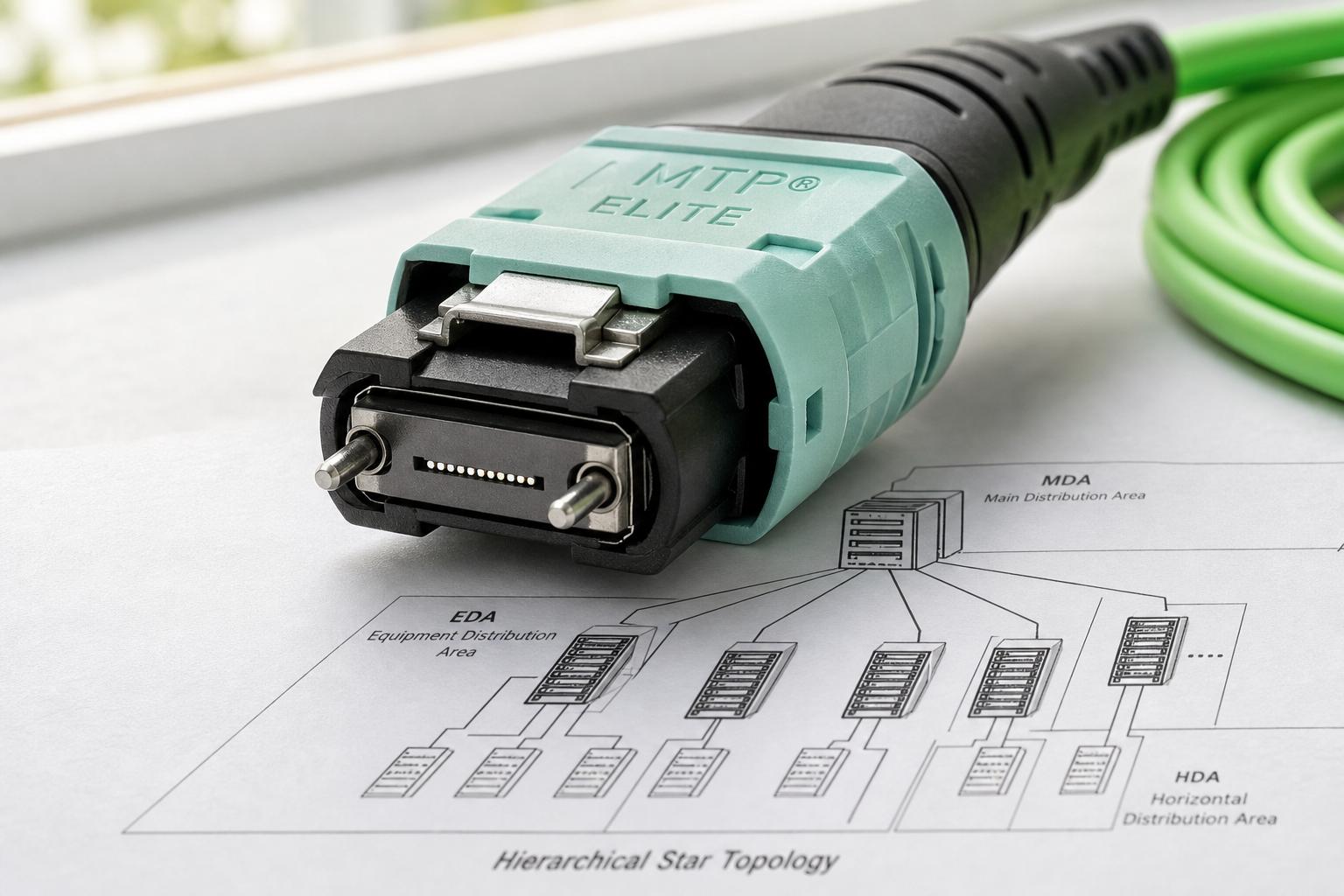
Fiber optic cabling is the physical layer that determines whether a data center's compute and network investments actually deliver their rated performance, and best practice in 2026 rests on four pillars: a standards-based design, correct fiber and connector selection, disciplined link budget engineering, and installation discipline that protects glass from damage during its operational life. The primary design references are the ANSI/TIA-942-C Telecommunications Infrastructure Standard for Data Centers, last revised in 2023 to address artificial intelligence (AI) workloads and sustainability [1], and the ANSI/BICSI 002-2024 best practices document, a 575-page, 17-chapter reference that most practitioners describe as the "ceiling" above TIA-942's regulatory "floor" [2]. TIA-942 organizes cabling into a hierarchical star topology using the main distribution area (MDA), horizontal distribution area (HDA), zone distribution area (ZDA), and equipment distribution area (EDA), and it rates data center redundancy on a four-level scale from Rated-1 (basic, single non-redundant path) to Rated-4 (fault tolerant, concurrently maintainable), a scheme conceptually aligned with the Uptime Institute's own four-tier system in which "the Tiers are progressive, so each Tier incorporates the requirements of the lower Tiers" [3] [4] [5].
Fiber and connector selection is the second pillar. Multimode fiber (OM3, OM4, and the newer OM5 wideband type) remains the lower-cost choice for links under roughly 550 meters at 10 Gigabit Ethernet (GbE) and under 100 to 150 meters at 40 and 100 GbE, while single-mode fiber (OS2) is required for longer campus and spine-layer runs and is now the default recommendation for any new AI-cluster buildout because it survives multiple transceiver generations without re-cabling [6]. Multi-fiber push-on (MPO) connectors and their trademarked MTP variant, engineered by US Conec with a metal pin clamp and a floating ferrule that can cut insertion loss to ~0.35 dB versus roughly ~0.75 dB for standard MT ferrules, have become the default high-density interface for parallel-optic 40G, 100G, 400G, and 800G transceivers [7] [8]. Getting polarity right across these multi-fiber assemblies is critical: the TIA-568 standard defines three methods (A, B, and C), and Method B, with its reversed trunk and identical patch cords at both ends, has become the de facto standard because it is the most installer-friendly and eliminates the crossover-jumper mistakes that are, by trade consensus, "the most common cause of data center fiber link failures during commissioning" [9].
The third pillar, link budget engineering, is where design meets physics. A loss budget sums fiber attenuation (roughly 3 dB/km for multimode at 850 nm and 1.0 dB/km for single-mode at 1,310/1,550 nm), connector loss (0.5 to 0.75 dB per mated pair under ANSI/TIA/EIA-568-C.3 and ISO/IEC 11801), and splice loss (about 0.3 dB per splice), then compares the total against the transceiver's power budget with a safety margin [10] [11]. Certification then proceeds through mandatory Tier 1 optical loss test set (OLTS) testing of insertion loss, length, and polarity, with optional Tier 2 optical time domain reflectometer (OTDR) characterization for troubleshooting and tighter-margin links [12] [13], while every connector is inspected against the IEC 61300-3-35 end-face cleanliness standard, which allows zero defects in the single-mode core zone [14].
The fourth pillar is installation discipline: pathway fill ratios capped around 25 to 40 percent depending on the referenced standard, both-end labeling to TIA-606-C, service loop management, and strict handling rules such as never pulling a cable by its connector and always fitting a pull-eye on runs over 100 feet [3] [15]. These practices matter more than ever because the global structured cabling market, valued at $13.7 billion in 2025 and forecast by Grand View Research to reach $32.4 billion by 2033 at an 11.5 percent compound annual growth rate (CAGR), is being reshaped by AI infrastructure, evidenced by Meta's up to $6 billion multiyear fiber supply agreement with Corning, Microsoft Azure's production deployment of hollow-core fiber, and Google's Jupiter network, which uses optical circuit switching to cut power by 40 percent and downtime by 50 times versus prior architectures [16] [17] [18].
Introduction and Background
This report answers the question of what constitutes fiber optic cabling best practice in the modern data center by working through four interlocking disciplines: the standards and topology that govern design, the fiber and connector choices that determine reach and density, the link budget mathematics that predict whether a link will work before it is ever tested, and the installation and testing procedures that turn a design into a certified, operational cable plant. It also addresses the practical questions that recur in every design review: what the difference is between an MPO and an MTP connector, how MPO polarity methods A, B, and C actually differ, how to calculate a fiber optic link budget from first principles, when single-mode fiber is mandatory versus when multimode remains the more economical choice, and how a cabling plant installed for 40G or 100G can be engineered to survive the jump to 400G, 800G, and beyond.
The stakes are rising because of two converging trends. First, hyperscale and AI infrastructure operators are deploying fiber counts an order of magnitude higher than a conventional enterprise server rack required just a few years ago, a shift driven by the parallel-optic fiber requirements of GPU back-end fabrics, CPU front-end networks, and storage networks operating side by side in the same rack. Second, the underlying standards themselves have been rewritten to keep pace: the ANSI/TIA-942-C revision published in 2024 explicitly addresses higher rack power densities, liquid immersion cooling, and the fiber types needed to support AI-era applications, while ANSI/BICSI 002-2024 expanded its own guidance on liquid cooling and energy optimization in the same window [20]. Data center designers, facility managers, and network engineers who have not revisited their cabling standards playbook since the 40G or 100G era are, in effect, designing against an outdated map. The sections that follow lay out the current map in detail, section by section, from the topology-level standards down to the microscope-level inspection criteria that decide whether an individual connector passes acceptance testing.
Foundational Standards and Design Architecture
TIA-942 and BICSI 002: Complementary, Not Competing
The starting point for any data center cabling design is understanding which standards actually govern it, because more than one applies and they are not interchangeable. ANSI/TIA-942, first published in 2005 and revised as version C in 2023, "specifies the minimum requirements for telecommunications infrastructure of data centers and computer rooms, including single tenant enterprise data centers and multi-tenant data centers" and is ANSI-accredited, giving it the authority of a formal American National Standard [21]. ANSI/BICSI 002-2024, by contrast, is a best practices document rather than a minimum-requirements standard: it runs to 575 pages across 17 chapters and 12 appendices covering everything from electrical and mechanical systems to commissioning and multi-site architecture, and it explicitly requires the designer to pair it with a base telecommunications standard such as TIA-942 [2]. The practical shorthand that has emerged among practitioners is that "TIA-942 as the 'floor' (minimum requirements) and BICSI 002 as the 'ceiling' (best practice target)," and the two documents even disagree on details such as whether an emergency power off (EPO) button should be installed absent a legal mandate, with BICSI recommending against it as an outage risk [22]. Outside North America, ISO/IEC 24764 and, in Europe, EN 50173-20 and EN 50600 serve equivalent roles, and most multinational data center portfolios reference more than one framework simultaneously so that the more stringent requirement governs wherever they conflict.
Distribution Areas and the Star Topology
Regardless of which base standard is referenced, the physical cabling architecture that TIA-942 recommends is consistent: a star topology built around five defined cross-connect and interconnect areas. Corning's application engineering literature, itself built around the ANSI/TIA-942-B standard, explains that "the standard defines five different cross-connect/interconnect areas: the main distribution area (MDA), intermediate distribution area (IDA), horizontal distribution area (HDA), zone distribution area (ZDA), and equipment distribution area (EDA)," which together represent the full path from the entrance room and core network equipment down to the individual rack [3]. The number of fibers required at each distribution area is not fixed; it is a function of network speed, logical architecture (point-to-point, full mesh, or spine-and-leaf), oversubscription ratio, and switch port configuration, and Corning's own modeling shows that four independent variables can each push a single cabinet's fiber count from a baseline of 8 fibers up past 60 or more depending on how they combine [3]. This is why a cabling design produced for a 10G, point-to-point enterprise network cannot simply be copied onto a 100G spine-and-leaf fabric: the same physical star topology can require anywhere from a dozen to several hundred fibers per cabinet depending on these variables, and TIA-569 provides the pathway fill guidance needed to make sure the resulting trunk counts actually fit in the tray that was designed to carry them.
Data Center Rated and Tier Classifications
A third layer of the standards landscape concerns redundancy classification. TIA-942 defines four Rated levels that describe the resilience of the site infrastructure, including its cabling distribution paths: Rated-1 is "Basic Site Infrastructure," described as "a data center which has single capacity components and a single, non-redundant distribution path serving the computer equipment" with "limited protection against physical events," while Rated-4 is "Fault Tolerant Site Infrastructure," defined as a facility with "redundant capacity components and multiple independent distribution paths serving the computer equipment which all are active" that "allows concurrent maintainability and one (1) fault anywhere in the installation without causing downtime" [4]. These ratings are conceptually parallel to the Uptime Institute's own four-tier classification system, under which "the Tiers are progressive, so each Tier incorporates the requirements of the lower Tiers," and a Tier IV facility specifically "add[s] fault tolerance to the Tier III topology" so that a single equipment failure does not affect IT operations [5]. TIA separately offers three certification types, Design, Facilities, and Ready, with facility certification valid for three years subject to interim surveillance audits [4]. For cabling designers specifically, the Rated level dictates whether a design needs a single non-redundant distribution path (Rated-1 or Rated-2) or fully diverse, concurrently maintainable A and B fiber paths from the MDA all the way to the EDA (Rated-3 and Rated-4), which in turn drives fiber count, pathway diversity, and patch panel redundancy decisions made at the very start of a project.
Fiber Type and Connector Selection
Single-Mode versus Multimode Fiber
The most consequential early decision in any cabling design is the choice between multimode fiber (MMF) and single-mode fiber (OS2, also called SMF). Multimode fiber has a larger core, typically 50 microns, that allows multiple light modes to propagate, and it is identified by the ISO 11801 standard into generations OM1 through OM5, each with distinct bandwidth, distance, and jacket-color characteristics [6]. OM3 fiber, with an aqua jacket, supports 10GbE to 300 meters and is rated for 40 and 100 Gigabit Ethernet parallel-optic links to roughly 100 meters, while OM4, backward compatible with OM3, extends 10GbE reach to 550 meters and supports 40/100 Gigabit Ethernet to about 150 meters using an MPO connector, and OM5, the newest generation with a lime-green jacket, is a wideband multimode fiber (WBMMF) engineered to support at least four wavelength-division-multiplexed channels and is backward compatible with OM4 [6]. Table 1 below summarizes the physical and practical differences among the five multimode generations.
| Type | Core Diameter | Jacket Color | Bandwidth @ 850nm | Max 10GbE Distance | Max 40/100GbE Distance |
|---|---|---|---|---|---|
| OM1 | 62.5/125 µm | Orange | 200 MHz*km | 33 m | Not supported |
| OM2 | 50/125 µm | Orange | 500 MHz*km | 82 m | Not supported |
| OM3 | 50/125 µm | Aqua | 2,000 MHz*km | 300 m | ~100 m |
| OM4 | 50/125 µm | Aqua | 4,700 MHz*km | 550 m | ~150 m |
| OM5 | 50/125 µm | Lime Green | 28,000 MHz*km | 550 m | ~150 m |
Source: FS.com multimode fiber comparison, compiled from ISO 11801 classifications.
As the table shows, every multimode generation runs out of reach well before a kilometer, which is why single-mode fiber, with its roughly 9-micron core, dominates any link that must span more than about 550 meters. FS.com's technical comparison notes plainly that light "travels a longer distance inside single mode cable than it does inside multimode," so multimode is "suitable for short haul application, allowing transmission distances of up to about 550m at 10Git/s," beyond which "single mode fiber is preferred" [6]. Cost follows a similar tiered logic across the whole physical layer: Leviton's transceiver survey notes that "copper is the least expensive solution to implement but supports shorter link distances and lower maximum data rates," that "multimode can handle higher speeds and support longer distances than copper but will come at a higher cost," and that single-mode optics remain "the only solution capable of delivering higher data rates such at 100 Gb/s (and higher) at the longer link distances required" for the spine tier [23]. That cost advantage, however, is now being weighed against a longevity argument that has become central to AI-era planning: single-mode fiber "installed today supports 400G to 800G to 1.6T to 3.2T upgrades through transceiver changes only," meaning the physical plant does not need replacement across multiple speed generations, whereas multimode's usable reach shrinks with every speed jump, for example from 400 meters at 10GBASE-S on OM4 down to 100 meters once the same link is upgraded to 100GBASE-SR4 [22] [23]. The practical guidance that has emerged is to keep multimode for short intra-row and storage connections where cost matters most, and to specify single-mode OS2 for anything in the spine, super-spine, or data center interconnect (DCI) tier, and increasingly for AI cluster fabrics regardless of distance.
MPO versus MTP Connectors
Once fiber type is settled, the connector interface for high-density and parallel-optic links is almost always some variant of the multi-fiber push-on (MPO) family. As one fiber cable manufacturer summarizes it, "MPO is a fiber connector type while MTP is a registered trademark of an MPO connector manufactured by US Conec," compliant with the IEC-61754-7 and EIA/TIA-604-5 (FOCIS 5) interface standards and typically available in 8, 12, 16, 24, or 32-fiber configurations [8]. MTP is not a separate connector family but "a trademark of US Conec for a version of the MPO connector with improved specifications," fully compliant with the same MPO standards and mechanically intermateable with generic MPO connectors, but built with a metal pin clamp instead of plastic, a floating MT ferrule instead of a fixed one, and elliptical stainless-steel guide pins instead of flat-tipped ones that generate less particulate debris on mating [7]. These mechanical refinements translate directly into measurable optical performance: "US Conec data shows that standard MT ferrules can reach ~0.75 dB (singlemode) or ~0.6 dB (multimode), whereas MT Elite® MTP® ferrules are limited to ≤0.35 dB in both cases," a difference that matters considerably once a link accumulates a dozen or more mated connector pairs across cassettes and patch cords [7]. As one vendor's blog summarizes the relationship, "all MTPs are MPOs but not all MPOs are MTPs," and the practical decision for a data center designer is whether the incremental cost of the branded connector is justified by its lower loss budget and its field-reconfigurable housing, which is increasingly the case in dense AI GPU cluster fabrics where every 0.1 dB of margin matters [8]. At the transceiver end, LC duplex connectors remain "the most popular fiber connection type" for lower-speed and point-to-point links because they are simple to manage from a polarity perspective, but MPO/MTP dominates any parallel-optic interface at 40G and above [23].
MPO/MTP Polarity Methods A, B, and C
Multi-fiber connectors introduce a problem that simple duplex LC jumpers do not have: with 8, 12, or more fibers in a single connector, the cable plant must guarantee that the transmit fiber at one transceiver lands on the correct receive fiber at the other end across every trunk, cassette, and patch cord in the channel. As one manufacturer's technical guide frames it, "MTP/MPO polarity refers to the logical relationship between transmit (Tx) and receive (Rx) fibers within an end-to-end fiber optic link," achieved through the coordinated interaction of fiber mapping inside the connector, key orientation (key-up or key-down), and the physical alignment pins that ensure male and female connectors mate correctly [24]. The TIA-568 standard resolves this with three defined polarity methods, and getting them right is not a cosmetic detail; as one installer-facing reference bluntly puts it, "MPO polarity is the most common cause of data center fiber link failures during commissioning" [9]. Method A uses a straight-through (Type A) trunk with a key-up connector on one end and a key-down connector on the other, so that "the fiber located in Position 1 (Tx) arrives at Position 1 (Tx) at the other end," which typically requires a crossover patch cord at one end to complete the transmit-to-receive alignment [25]. Method B instead uses a reversed (Type B) trunk with key-up connectors on both ends, so that "the fiber located in Position 1 (Tx) arrives at Position 12 (Rx) at the opposite end," a full fiber-position reversal that lets identical, straight patch cords be used at every cabinet [25], which is precisely why this configuration "make[s] MTP/MPO Type B cables the most commonly recommended type for universal applications, especially in high-speed parallel optics like 40G/100G" [24]. Method C achieves a similar operational simplicity by flipping each adjacent fiber pair within the cable itself rather than reversing the entire array, but it is now comparatively rare in new data center builds [25]. Because "Method B is the most common in new data centers because it minimizes the chance of polarity mistakes at the cabinet," it has become the effective default for greenfield deployments [9]. Table 2 summarizes the three methods.
| Aspect | Method A | Method B | Method C |
|---|---|---|---|
| Trunk type | Type A (straight-through) | Type B (reversed) | Type C (pair-swapped) |
| Key orientation | Key-up to key-down | Key-up to key-up | Key-up to key-down |
| Patch cord, end A | Standard A-to-A | Standard A-to-A | Standard A-to-A |
| Patch cord, end B | A-to-B crossover | Standard A-to-A | Standard A-to-A |
| Where the flip lives | In the end-B patch cord | Inside the trunk | Inside the trunk (pair-swap) |
| Common in new builds (2026) | Occasional, legacy-influenced | Most common default | Rare |
Source: ShopFiberOptic and Sumitomo Electric Lightwave MPO polarity guides [9].
A polarity mismatch is invisible to a visual check and to most quick continuity tests; it produces a channel that appears physically intact but carries no traffic because transmit and receive fibers never line up, and it is only reliably found with a visual fault locator, a fiber identifier, or a full Tier 1 test [9]. A related but distinct rule applies when parallel-optic transceivers connect through a direct MPO patch cord with no intervening cassette: "for SR4 transceivers connected directly with an MPO patch cord, you need a Type B (reversed) MPO patch cord," because a straight-through Type A cord will not deliver transmit fibers to the correct receive positions in that direct-attach scenario [9]. Because "mixing different polarity methods within a single channel is not recommended" and can easily "result in Tx-to-Tx or Rx-to-Rx connections, leading to link failures," the single most effective operational safeguard is procedural: choose one method for the entire facility, document it on every patch panel, and order trunks, cassettes, and patch cords from a single, coordinated specification so that mismatched vendor defaults never enter the plant [24].
Link Budget Engineering and Certification Testing
Calculating the Optical Loss Budget
A power budget describes how much optical loss a transceiver pair can tolerate before the receiver stops working reliably, calculated as the difference between minimum transmit power and minimum receiver sensitivity; a loss budget is the engineer's estimate of how much loss the specific cable plant will actually introduce, and the difference between the two is the design margin [11]. Juniper's networking documentation expresses the power budget formula simply as PB = PT minus PR, where PT is minimum transmitter output power and PR is minimum receiver sensitivity, both expressed in decibel-milliwatts (dBm), yielding a power budget expressed in decibels [26]. The resulting power margin (PM) is then the power budget minus the link loss (LL), or PM = PB minus LL, and "PM greater than zero indicates that the power budget is sufficient to operate the receiver" [26]. To calculate the link loss itself, the industry references minimum acceptable component loss values published in "ANSI/TIA/EIA-568-C.3 and ISO/IEC 11801:2002," which set a mated connector pair at 0.75 dB, a splice at 0.3 dB, multimode fiber attenuation at 3.5 dB per kilometer at 850 nm, and single-mode fiber attenuation at 1.0 dB per kilometer at both 1,310 nm and 1,550 nm, though installers typically use the tighter values that manufacturers actually achieve in practice, such as 0.5 dB per connector and 3.0 dB per kilometer at 850 nm [10].
A worked example makes the calculation concrete. For a multimode premises local area network (LAN) link operating at 850 nm with a 500-meter cable run, four mated connections, and no splices, the Fiber Optic Association's Jim Hayes calculates fiber loss as "Length of cable plant: 500 meters... 0.5 km X 3 dB/km = 1.5 dB," connector loss as four connections at 0.5 dB each for 2.0 dB, and no splice loss, so that "Total loss = 1.5 dB fiber loss + 2.0 dB connection loss + 0 dB splice loss = 3.5 dB" [11]. Because the communications equipment in this example has a 7 dB power budget, this design leaves a 3.5 dB margin, comfortably positive and resilient to some future connector additions or fiber degradation [11]. Juniper's own example for a single-mode outside-plant link works the same logic in reverse to solve for margin: starting from a 13 dB power budget, the calculation subtracts 2 kilometers of fiber loss at 1 dB per kilometer, five connector losses of 0.5 dB each, two additional connector losses of 0.5 dB each, and a final 0.5 dB allowance, resolving to a power margin of 7 dB, a comfortably positive result confirming the link has sufficient power [26]. The generalizable lesson for data center designers is that a loss budget must be recalculated for the actual connector and splice count in a specific channel, not assumed from a rule of thumb, because the CABLExpress installation guidance notes that a cabling design's "goal is to maximize efficiency using loss budgets productively," which is only possible if the budget reflects the real topology rather than a generic estimate [15].
Tier 1 and Tier 2 Fiber Certification
Once a link is installed, it must be certified against its calculated budget before it is trusted with production traffic. CommScope's own field-testing guidance frames the acceptance process as three sequential phases, "visual inspection," "testing," and "documentation," and notes that the documentation phase "is the most prone to neglect" even though "much of the testing value is lost" without it [13]. The industry-standard two-tier testing framework starts with Tier 1 testing, performed with an optical loss test set (OLTS), which certifies total insertion loss, length, and polarity for every fiber link; Tier 2 testing adds an optical time domain reflectometer (OTDR) characterization but does not replace Tier 1, since "Tier 2 testing does not replace the total insertion loss measurements taken during Tier 1 testing. Tier 2 testing requires Tier 1 and is used as a complementary evaluation" [12]. An OTDR works by sending "pulsed laser diodes to transmit high-power light pulses into the fiber" while "high-gain light detectors" measure any light reflected back from connectors, splices, bends, or breaks, producing a graphical trace that pinpoints the location and magnitude of each event along the link, which makes it the preferred troubleshooting tool for locating a specific bad connector or splice rather than merely knowing that a link has failed [12]. Proper OTDR technique requires launch and tail fibers at both ends of the link to overcome the instrument's dead-zone limitations near the near-end and far-end connectors, and best practice calls for bidirectional testing, averaging the loss measured from each direction, because a single-direction OTDR trace can under- or overstate a connector's true loss depending on the mismatch between the two mated fiber cores [12]. CommScope's testing checklist likewise calls for visual verification of "infrastructure," "cable placement," "cable termination," "connector end-faces," and "the labeling of all components" before any electronic test equipment is connected [13], while CABLExpress's own installation guidance adds that certification documentation should capture the measured attenuation values against tested limits, the link length, the date and personnel performing the test, and the identification and calibration date of the field test instrument, all packaged into a formal closeout report at project completion [15].
Connector Inspection and Cleaning to IEC 61300-3-35
Before any link is even tested for loss, every connector end-face must pass a visual cleanliness inspection, because contamination is the single most common cause of an otherwise correctly engineered link underperforming its calculated budget. "IEC 61300-3-35 is the international standard for fiber optic connector end-face cleanliness," and it exists precisely because before its adoption, "every vendor had its own inspection criteria," making a pass on one company's scope meaningless to another operator [14]. The standard defines four concentric zones around the fiber core, with defect tolerance tightening the closer a flaw sits to the light path, and the rule for the innermost zone is absolute: "single-mode allows zero defects," because "a 1 micrometer particle on a 9 micrometer core covers more than 10% of the optical mode, which is enough to cause a measurable insertion loss spike," while the larger multimode core tolerates a small number of sub-micron defects before failing [14]. It is worth being precise about what a passing grade actually means: "PASS means the connector meets the published IEC defect limits," not that the connector is pristine, since it can still carry several small permitted defects outside the critical zones [14]. The corresponding field workflow, as CABLExpress's own best practices document lays out, is to leave protective caps on until immediately before mating, then "inspect the surface of the fiber optic glass end point (ferrule) with a microscope and, if needed, clean the connector with a one-click cleaner," followed by a second inspection after cleaning and before the connector is ever plugged in [15]. This inspect-clean-inspect-connect sequence, executed on both sides of every mated pair, is the single cheapest and most effective quality control step available in the entire cabling process.
Installation, Pathway, and Cable Management Best Practices
Pathway Fill Ratios and Segregation
Correct cable design is worthless if the physical pathway cannot actually accommodate the resulting fiber count, and pathway sizing is one of the areas where sources genuinely disagree, a discrepancy worth surfacing honestly rather than glossing over. Corning's structured cabling white paper, drawing on TIA-569, states that this standard "provides calculations to understand what percentage of tray/conduit/raceway is taken up by cabling along with a recommendation that the individual maximum fill ratio not exceed 25 percent," and it further cautions that "a 50 percent fill ratio actually uses up an entire pathway, because the spaces between cables are part of the equation," meaning fill percentages are far less forgiving than the raw math suggests [3]. A more recent AI-infrastructure trade analysis, by contrast, cites a "cable tray sizing at 40% fill ratio maximum" recommendation for new GPU cluster pathway design, a figure roughly 60 percent higher than Corning's 25 percent guidance [22]. Designers should treat 25 percent as the conservative, TIA-569-sourced baseline for pathways expected to see substantial future growth, and reserve higher fill ratios only where a specific engineering review confirms adequate airflow and cable protection; in either case, the calculation should happen before conduit or tray is ordered, not after fiber counts are finalized. Segregation matters as much as sizing: CABLExpress recommends that "copper and fiber trunk/bulk runs should be separated in either the same tray or run in separate trays" to reduce the potential for loss from kinks and pressure build-up, a principle that AI-cluster pathway guidance extends to power distribution as well, since high-voltage DC cabling can introduce electromagnetic interference into an adjacent data tray if the two are not physically separated [15].
Labeling, Documentation, and Service Loops
Every cable in a modern data center needs to be identifiable months or years after installation, without relying on institutional memory. TIA-606-C is the governing administration standard, and CABLExpress's guidance is direct that "your label numbering scheme should match the TIA-606-C published standards for all jumpers and patch cords," identified by cabinet number, rack unit, and port location, with longer trunk cables labeled at both ends with length, origination, and destination information so an installer never pulls the wrong 200-foot cable through its designed route [15]. Panduit's own identification guide, built around the predecessor TIA-606-B standard, recommends a coordinate-based scheme in which "component locations are determined using an X-Y coordinate system based on the floor tile system in the data center space," so that a cabinet, panel, and port can each be decoded directly from its label without consulting a separate database, and it notes that "many of today's physical infrastructure disruptions are caused by moves, adds, or changes within the environment," which is precisely what a consistent labeling scheme is designed to prevent [27]. Service loops, extra cable length coiled to allow future repositioning of patch panels, should be kept short (typically three to six feet), managed with hook-and-loop fastener in a circle with at least four mounting points to prevent unraveling, and never mounted inside a conveyance where they could interfere with access to hardware [15].
Handling, Bend Radius, and Pulling Tension
Fiber optic glass is remarkably strong in tension along its axis but intolerant of sharp bends or point pressure, and most in-service failures trace back to installation-phase mishandling rather than a manufacturing defect. CABLExpress's field guidance is blunt: "don't use zip-ties, use Velcro" when securing fiber runs, because zip ties can pinch the cable jacket and damage the glass beneath it, and the only zip-tie exception is the reinforced furcation point at each end of a trunk, which is specifically designed with a metal sleeve to protect the fiber [15]. On pulling tension, the rule is equally direct: never stretch a cable that is too short, never use the connectors themselves to pull a cable through its route, and "always have a pull-eye added to a cable longer than 100 feet," since warranties do not cover damage caused by mishandling during installation [15]. Bend radius is the physics behind that handling rule: for standard single-mode fiber, "the recommended minimum bend radius is 30 mm," and "bending below about 15 mm causes severe loss that can take the link offline," which is why newer bend-tolerant G.657 fiber grades exist specifically for the tight patch panel and under-floor routing found in high-density cabinets [28]. The most common of these, G.657.A2, allows a 7.5 mm bend radius and "is the de facto standard for FTTH drop cable, MDU (multi-dwelling unit) indoor wiring, and any installation where the cable must navigate tight pathways," while remaining fully compatible with standard G.652.D fiber for splicing and connecting [28].
Migration Pathways: 40G to 100G to 400G and Beyond
Fiber Count and Architecture Planning
Network speed migration is rarely a simple swap of one transceiver for a faster one; it typically changes the number of fibers a given port requires, and getting this wrong is the most common cause of a "future-proof" cabling plant becoming obsolete within a single refresh cycle. Corning's fiber-count modeling shows that "10G only takes 2 fibers to support; 40G can operate over 2 or 8 fibers; and 100G takes 2, 8, or even 20 fibers depending on the transceiver," meaning the jump from one speed generation to the next does not have a single, predictable fiber-count multiplier and instead depends heavily on which transceiver family a given switch vendor selects [3]. Leviton's transceiver survey confirms the trend on the ground: "cloud provider networks have operated at 40 Gb/s uplinks to the switch and 10 Gb/s from switch to server. These networks are now moving to 100 Gb/s uplinks and 25 Gb/s downlinks to the server, with some even preparing to migrate to 200 and 400 Gb/s uplinks and 50 and 100 Gb/s at the server," a stair-step migration pattern that has repeated at every subsequent generation since [23]. A key architectural tool for absorbing this uncertainty is the high-fiber-count trunk terminated in modular cassettes: a single Base-24 MPO trunk, for example, "can contain 2-, 8-, 16-, 20- or 24-fiber strand transceiver connections," meaning the same physical backbone cable can support the full range of 25 Gb/s and 100 Gb/s transceiver options simply by changing the cassette at each end, without touching the trunk itself [23]. Corning's own comparison of jumper-based, medium-trunk, and high-fiber-count-trunk deployment strategies for a real Cisco spine-and-leaf reference architecture is stark: an approach using individual 2-fiber jumpers required more than 3,000 individual cables and over 6,000 connectors to test, document, and troubleshoot for a single fabric, while consolidating the same fiber count into six 576-fiber trunks cut that same workload down to just six cables and 576 connectors [3].
The 800G to 1.6T Transition
As of mid-2026, the industry timeline shows 400G as the mainstream commodity speed through 2024, 800G reaching broad production in 2025, and 1.6T entering early hyperscale production in 2025 and 2026 before wider availability later in the decade, with the Open Systems Form Factor Extra Density (OSFP-XD) module emerging as the primary 1.6T form factor [22]. The pragmatic guidance for cabling investment at this transition is to specify infrastructure that survives the jump, since OS2 single-mode fiber, MPO-16 (16-fiber) trunk assemblies, and OSFP cage infrastructure are all reported to carry forward from 800G into 1.6T without replacement, whereas copper direct-attach cables, active optical cables, and any switch hardware locked into the OSFP-XD form factor generally do not, because they are engineered for a fixed lane rate. This asymmetry is why many designers now specify 16-fiber MPO trunks even when only 8 fibers are being actively used for a current 800G deployment, since the incremental cost of the extra 8 spare fibers is modest compared with the cost of re-cabling an operational cluster once it upgrades. The connector interface itself is evolving alongside the trunk count: MPO-12 remains the standard for 400G and legacy 100G links, while a new, higher-fiber-count MMC connector family is emerging as the interface for 800G and beyond, and Corning's own 2026 product slate specifically added "a new 32-fiber MMC® connector option" alongside its existing 12, 16, and 24-fiber configurations "for space constrained, high performance network environments" [29]. Corning is independently pushing density further still with a multicore fiber solution that packs four times the capacity into the same standard 125-micron cladding footprint, which the company states "requires up to 75% fewer connectors, reduc[es] cable mass by up to 70% and help[s] cut installation time by up to 60%" for equivalent capacity [29].
Emerging Optical Technologies
Beyond the near-term 800G-to-1.6T transition, several optical technologies are moving from research toward commercial deployment and will reshape cabling best practice further before the decade closes. Hollow-core fiber (HCF), which transmits light through an air core rather than solid glass, is already in production use at Microsoft Azure, where it delivers "up to 47% faster data transmission and approximately 33% lower latency compared to conventional Single Mode Fiber," according to Microsoft's own network engineering team [30]. Co-packaged optics (CPO), which integrates photonic components directly onto or beside the switch silicon rather than through a field-pluggable transceiver, is being showcased by Corning as part of an end-to-end system that includes detachable fiber-to-chip connectors and bend-resilient fiber optimized for the short interconnect lengths involved, aimed at both scale-out network fabrics and future GPU scale-up interconnects [29]. Multicore fiber, which packages several parallel light-carrying cores inside a single strand of standard-diameter glass, is a complementary density play from the same vendor rather than a competing technology, and Corning specifically markets its version alongside a new micro cable that packs 1,728 fibers, "double the fiber... in the same space as Corning's most recent micro cable solution," for long-distance campus and data center interconnect runs [29]. None of these technologies displaces the fundamentals covered earlier in this report; loss budgets, polarity discipline, end-face cleanliness, and pathway planning apply just as rigorously to a hollow-core or multicore fiber plant as they do to conventional OS2, and in several cases the tolerances involved are tighter, not looser, than the standard fiber types most designers are accustomed to specifying today.
Data Analysis and Evidence
The market data behind fiber optic cabling best practice confirms that the discipline is scaling with, not lagging, the broader data center buildout. Grand View Research values the global structured cabling market at $13.7 billion in 2025, projecting growth to $15.1 billion in 2026 and $32.4 billion by 2033, a compound annual growth rate of 11.5 percent from 2026 to 2033, with North America holding the largest regional revenue share at 31.0 percent in 2025 [16]. Notably, copper cabling still led the overall structured cabling product mix with over 48.0 percent revenue share in 2025, because the majority of the market's dollar volume flows through local area network (LAN) applications rather than data centers, but Grand View Research's analysts specifically flag that "fiber optic cables are experiencing rapid growth in the structured cabling market due to their superior bandwidth and transmission speeds," driven by cloud computing, AI workloads, and 5G infrastructure [16]. This bifurcation matters for interpreting cabling-market statistics generally: enterprise LAN volume is dominated by copper, while the data center application segment, which the same research firm separately identifies as a fast-growing category driven by hyperscale and colocation investment, is overwhelmingly a fiber story.
On the physical-layer performance side, the numbers reinforce why fiber selection and connector quality carry the weight this report has placed on them. A standard MT ferrule mated pair can present up to 0.75 dB of insertion loss in single-mode applications, while a premium MT Elite ferrule caps that same measurement at 0.35 dB, a difference of more than 50 percent on every single mated connection in a channel [7]. Multiply that difference across a channel with a dozen mated pairs, which is routine in a modern cross-connect architecture with MDA, HDA, and EDA cassettes, and the aggregate margin difference easily exceeds a full decibel, which in turn can be the entire difference between a link that passes certification with headroom and one that fails outright. On the standards-adoption side, TIA reports that its ANSI/TIA-942-C revision, published in 2024, was updated specifically "to address the massive growth of data, emerging technologies like artificial intelligence (AI), and the growing need for sustainability," reflecting the industry's own acknowledgment that pre-AI-era cabling guidance is no longer sufficient on its own [1]. Fiber density figures published by AI-infrastructure trade analysts illustrate the scale of the shift, though these specific per-rack fiber counts are drawn from third-party vendor and analyst estimates rather than an official standards body and should be read as illustrative industry benchmarks rather than fixed specifications: one such analysis reports that a single AI GPU rack can require several hundred individual single-mode fibers, a figure it attributes to broader industry research indicating that "generative AI data Centers require ten times more optical Fiber than conventional server racks in the same footprint" [22]. Whatever the precise multiplier for a given GPU generation, the directional conclusion holds across every source reviewed for this report: AI-era racks consume dramatically more fiber, more connectors, and more pathway capacity per unit of floor space than the enterprise racks that most existing cabling standards and legacy pathway designs were originally sized for.
Case Studies and Real-World Examples
Meta and Corning: a $6 Billion Fiber Supply Agreement
In January 2026, Corning Incorporated and Meta Platforms announced "a multiyear, up to $6 billion agreement to accelerate the buildout of the most advanced data centers in the United States to support Meta's apps, technologies, and AI ambitions," under which "Corning will supply Meta with its newest innovations in optical fiber, cable, and connectivity solutions" [17]. The agreement is structured around a manufacturing capacity expansion at Corning's Hickory, North Carolina, optical cable facility, where Meta will serve as the anchor customer, and Corning projects the deal will help sustain "a skilled workforce of more than 5,000" employees across its North Carolina fiber and cable operations while growing state employment by 15 to 20 percent [17]. This case illustrates, at hyperscale, exactly the fiber-versus-transceiver longevity logic discussed earlier in this report: Meta is committing multi-year capital specifically to single-mode fiber and connectivity infrastructure rather than transceivers, on the premise that the physical fiber plant will remain useful across several successive speed-generation upgrades even as GPU and switch silicon iterate far more rapidly.
Microsoft Azure: Hollow-Core Fiber in Production
Since 2023, "Microsoft has deployed HCF across multiple Azure regions, with production links meeting performance and reliability targets," making Azure the first major hyperscaler to move hollow-core fiber, a technology once confined to university and vendor laboratories, into revenue-generating cloud infrastructure [30]. In September 2025, Microsoft announced it would scale HCF manufacturing through new strategic collaborations with Corning and Heraeus Covantics, moving the fiber, originally developed in-house after Microsoft's 2022 acquisition of Lumenisity, a spin-out of the University of Southampton's Optoelectronics Research Centre, from a bespoke research product toward an industrial supply chain [30]. The underlying physics driving Microsoft's investment was confirmed in a peer-reviewed paper published in Nature Photonics, in which University of Southampton researchers working with Azure Fiber demonstrated "the lowest signal loss ever recorded for optical fibers (<0.1 dB/km) using research-grade DNANF HCF technology," a result that, if it translates into commercial-scale production fiber, would represent a meaningful reduction in the attenuation figures this report's loss-budget calculations have relied on throughout [30]. This case demonstrates that even the most fundamental input to a link budget calculation, the fiber's own attenuation coefficient, is not a fixed constant but an active area of commercial research and development at hyperscale.
Google Jupiter: Optical Circuit Switching at Warehouse Scale
Google's Jupiter data center network, first documented publicly at 30,000-server scale in 2015, has grown to the point where "today, Jupiter supports more than 6Pb/sec of datacenter bandwidth," an increase Google attributes largely to the introduction of optical circuit switching (OCS) alongside its existing software-defined networking control plane [18]. An optical circuit switch "maps an optical fiber input port to an output port dynamically through two sets of micro-electromechanical systems (MEMS) mirrors that can be rotated in two dimensions to create arbitrary port-to-port mappings," which allows Google to reconfigure the logical topology of its network fabric without physically re-cabling a single fiber, even as the electrical transceiver technology behind those fibers moves from 40 Gb/s to 100, 200, and 400 Gb/s over time [18]. Google reports that this architecture delivers measurable operational gains over the best known alternatives, "reducing flow completion by 10%, improving throughput by 30%, using 40% less power, incurring 30% less cost, and delivering 50x less downtime" [18]. This case illustrates the cabling-adjacent principle running through this entire report from a different angle: Google's own conclusion was that the physical fiber and optical layer, not the electrical switching silicon, was the correct place to solve the problem of building a network that could absorb successive transceiver-speed generations without a wholesale rewiring event, the same lesson smaller operators are now applying at rack scale when they choose OS2 fiber and spare MPO-16 trunk positions specifically to survive the 800G-to-1.6T transition.
Implications and Future Directions
The evidence assembled in this report points toward several structural shifts in how data center operators should approach fiber optic cabling over the next several years. First, the traditional calculus that treated multimode fiber as the default, cost-driven choice for anything under a few hundred meters is eroding for new construction, because single-mode fiber's ability to absorb multiple transceiver-speed generations without physical re-cabling, as demonstrated by Meta's own multi-billion-dollar single-mode-focused supply commitment to Corning, increasingly outweighs multimode's lower up-front connector and transceiver cost, at least for any link expected to remain in service through more than one speed migration [17]. Second, connector density is climbing faster than most legacy pathway infrastructure was designed to absorb, and the practical response, evident in Corning's own 2026 product roadmap of 32-fiber MMC connectors and multicore fiber solutions delivering four times the density in the same cladding footprint, is that vendors are racing to increase fiber count per physical connector and per cable cross-section rather than simply asking facility operators to widen their cable trays indefinitely [29]. Third, polarity and end-face cleanliness discipline, historically treated as a junior-technician-level installation detail, is becoming a design-phase decision, since choosing Method B polarity and specifying pre-terminated, factory-tested MPO assemblies at the outset of a project materially reduces the commissioning-phase failure rate that has made polarity errors "the most common cause of data center fiber link failures during commissioning" [9].
Looking further ahead, the emergence of hollow-core fiber in production at Microsoft Azure and optical circuit switching at production scale within Google's Jupiter fabric both suggest that the boundary between "passive cabling" and "active network element" is blurring. A cabling plant that can be dynamically reconfigured at the optical layer, without a technician physically re-patching a single connector, changes the calculus for how much spare fiber capacity a design should build in up front, since the marginal cost of adding capacity later shifts from a labor-intensive re-cabling project toward a software-driven reconfiguration exercise, at least for operators with access to OCS infrastructure [18]. At the same time, standards bodies are still catching up: TIA-942 was last fully revised in 2023 and BICSI 002 in 2024, and both documents will need further updates as co-packaged optics, multicore fiber, and hollow-core fiber move from vendor showcase products toward mainstream specification items with their own connector geometries, splice procedures, and loss-budget assumptions. Data center operators planning cabling infrastructure with a 10 to 15-year service life, the horizon typically assumed for a properly engineered physical layer, should build contractual and design flexibility into their specifications now, rather than assuming that the OS2 single-mode, MPO-12/16, Method B polarity baseline described throughout this report will remain unchanged for the full duration of that service life.
Frequently Asked Questions (FAQs)
What is the actual difference between an MPO and an MTP connector? MPO is the generic multi-fiber push-on connector family defined by the IEC-61754-7 and EIA/TIA-604-5 standards, while MTP is a trademarked, mechanically enhanced version of that same connector made by US Conec, distinguished by a metal pin clamp, a floating ferrule, and elliptical guide pins that together reduce insertion loss and improve durability under repeated mating cycles [8] [7]. All MTP connectors are MPO connectors, but not every MPO connector is an MTP.
How is a fiber optic link budget calculated? Sum the expected fiber attenuation (distance in kilometers multiplied by the dB/km value for the fiber type and wavelength), the connector loss (typically 0.5 dB per mated pair for premium connectors), and the splice loss (about 0.3 dB per splice), then subtract that total link loss from the transceiver's power budget, itself the difference between minimum transmit power and minimum receiver sensitivity, to arrive at a positive power margin [11] [26].
Which is better for a data center, single-mode or multimode fiber? Neither is universally better; multimode (OM3, OM4, OM5) remains the more economical choice for intra-row links under roughly 100 to 550 meters depending on speed, while single-mode OS2 is required beyond that range and is now the recommended default for AI cluster fabrics of any distance because it supports multiple future transceiver-speed upgrades without re-cabling [6] [23].
What is the difference between MPO polarity Method A, B, and C? Method A uses a straight-through trunk plus a crossover patch cord at one end; Method B uses a reversed trunk with identical patch cords at both ends and is the most common choice in new builds; Method C uses a pair-swapped trunk and is largely obsolete in new data center construction [9] [25].
What standard governs data center fiber cabling design? ANSI/TIA-942-C is the primary ANSI-accredited requirements standard in North America, defining the MDA/HDA/ZDA/EDA distribution architecture and the Rated-1 through Rated-4 redundancy classification, while ANSI/BICSI 002-2024 supplies best practice guidance that must be paired with TIA-942 or an equivalent base standard, alongside the Uptime Institute's own four-tier facility classification system [21] [2] [5].
Is Tier 2 OTDR testing necessary, or is Tier 1 enough? Tier 1 optical loss test set (OLTS) testing of insertion loss, length, and polarity is mandatory for every fiber link; Tier 2 OTDR characterization is a complementary, optional layer used for troubleshooting or when a customer specification demands tighter visibility into individual connector and splice performance, and it never replaces Tier 1 [12] [13].
How should cabling be planned for a 40G to 100G to 400G migration? Specify high-fiber-count trunks terminated in modular cassettes rather than individual jumpers, since a single Base-24 or larger trunk can be reconfigured to support multiple transceiver generations by changing only the end cassettes, and favor single-mode fiber with spare MPO-16 fiber positions so the physical plant, rather than only the transceivers, survives the next speed jump [23] [22].
Conclusion
Fiber optic cabling best practice in the modern data center is not a single checklist but the intersection of four disciplines that must be engineered together: a standards-based topology drawn from TIA-942 and BICSI 002, a fiber and connector strategy that matches reach and density requirements to single-mode or multimode fiber and to MPO or MTP connectors, a link budget calculated from real component counts rather than assumed margins, and an installation regime that protects glass, enforces polarity discipline, and documents every connection to TIA-606-C. Each of these disciplines has its own body of technical detail, from the 25 percent pathway fill guidance drawn from TIA-569 to the zero-defect requirement in the single-mode core zone of IEC 61300-3-35, but they share a common thread: the cost of getting any one of them wrong compounds over the operational life of the facility, whether that cost shows up as a stranded GPU cluster waiting on a re-cabling project, a commissioning delay traced to a Method A trunk mistakenly paired with Method B cassettes, or a link that fails certification because its as-built connector count was never checked against its calculated loss budget.
The market and case-study evidence gathered in this report all point in the same direction. The structured cabling market's shift toward fiber, the multi-billion-dollar single-mode fiber commitments now being signed by hyperscale operators, and the production deployment of technologies like hollow-core fiber and optical circuit switching all confirm that the physical layer is receiving a level of design attention it did not receive a decade ago, precisely because AI and cloud workloads have made the consequences of getting it wrong far more expensive. For a data center design team working in 2026, the practical takeaway is to treat cabling architecture, fiber selection, polarity method, and testing regime as first-order decisions made at the earliest stage of a project, documented and specified with the same rigor as power and cooling design, rather than as details to be resolved by whichever installer arrives on site during the final weeks of construction.
External Sources (30)
About
GPUSmith
Plan and build private AI compute with GPU Smith. We connect workload requirements with GPU hardware, networking, deployment and operating decisions so your infrastructure fits the work it must perform.
GPU Smith provides independent engineering and research for private AI infrastructure. We help technical buyers and operators reason about GPU workload sizing, hardware selection, procurement, deployment and inference operations, from the compute system to the networking, power and cooling requirements around it.
Start with the workload
Useful infrastructure decisions begin with the models, data, throughput, latency and operating constraints a team actually has. GPU Smith helps connect those requirements with system design and deployment choices. The goal is a privately controlled AI environment whose capacity and operational demands are understood before a purchasing decision.
Hardware and supplier research
Our public reference library covers GPUs, complete systems and networking components. The server-vendor directory and manufacturing research help teams investigate suppliers, compare options and follow sources behind technical claims. We distinguish manufacturer specifications from measured benchmarks and advertised capabilities from tested configurations. Reference pages are research resources, not a live inventory listing or a binding equipment quote.
Deployment and operations
GPU Smith's engineering scope includes infrastructure integration, networking, power, cooling and the practical operation of inference workloads. Our published articles explain the tradeoffs behind deployment, procurement and ongoing operations so teams can ask better questions and document decisions.
Work with GPU Smith
Explore the hardware library, GPU references, networking references and vendor research. Contact GPU Smith with your workloads and deployment constraints to discuss a project and confirm current scope, pricing and availability.
Inclusion of a manufacturer or product in our research does not imply a partnership, certification or endorsement.
Disclaimer
This document is provided for informational purposes only. No representations or warranties are made regarding the accuracy, completeness, or reliability of its contents. Any use of this information is at your own risk. GPUSmith shall not be liable for any damages arising from the use of this document. This content was generated with assistance from artificial intelligence tools, which may contain errors or inaccuracies. Readers should verify critical information independently. All product names, trademarks, and registered trademarks mentioned are property of their respective owners and are used for identification purposes only. Use of these names does not imply endorsement. This document does not constitute professional or legal advice. For specific guidance related to your needs, please consult qualified professionals.