GPUSmith Article
GPU Data Center Cooling Design: CRAC, CRAH and Liquid Cooling
Inside this article
- 01Executive Summary
- 02Introduction and Background
- 03Cooling Load Fundamentals: Why GPU Racks Broke Traditional Data Center Design
- 04Air Cooling Systems: CRAC and CRAH Units Explained
- 05Airflow Management: Hot Aisle/Cold Aisle Containment and Best Practices
- 06Liquid Cooling Architectures: Direct-to-Chip, Rear-Door, and Immersion
- 07Chiller Plant and Heat Rejection Design
- 08Calculating Cooling Capacity and Designing for Redundancy
- 09Data Analysis and Evidence
- 10Case Studies and Real-World Examples
- 11Implications and Future Directions
- 12Frequently Asked Questions (FAQs)
- 13Conclusion
Executive Summary
GPU data center cooling design has shifted from a facilities afterthought to the primary constraint on artificial intelligence (AI) infrastructure deployment. Rack power densities that averaged 2 to 4 kilowatts (kW) fifteen years ago now routinely reach 60 kW in high-density air-cooled halls [1], while a single NVIDIA GB200 NVL72 rack requires 120 kW of direct liquid cooling capacity [2] and its successor, the GB300 NVL72, can draw more than 120 kW per rack in production deployments [3]. Equinix reports that GPU racks are already reaching 200 kW and trending toward 1 megawatt (MW) per rack [4]. This report explains, as of July 2026, the full engineering stack that data center operators use to remove this heat: computer room air conditioner (CRAC) and computer room air handler (CRAH) systems, hot aisle and cold aisle containment, direct-to-chip liquid cooling, rear-door heat exchangers, immersion cooling, chiller and cooling tower plant design, and the capacity-sizing math that ties them together.
The central finding is that air cooling alone can no longer support GPU-class density. Water and other liquids are, according to engineering guidance, "far more efficient at transferring heat than air, anywhere between 50 and 1,000 times more efficient" [5], which is why Dell'Oro Group's Data Center Liquid Cooling Advanced Research Report found liquid cooling has "crossed a critical threshold" and forecasts the market will roughly double in 2025 to nearly $3 billion in manufacturer revenue before reaching approximately $7 billion by 2029 [6], with single-phase direct liquid cooling (DLC) remaining the dominant architecture and GPU thermal design power (TDP) projected to exceed 4,000 watts (W) by 2029 [6]. Yet the Uptime Institute's 2025 Global Data Center Survey found that most facilities still cluster in the 10 kW to 30 kW rack range, with "few facilities exceed[ing] 30 kW" [7], and the industry's average power usage effectiveness (PUE) has held flat at 1.54 for a sixth consecutive year [8]. This gap between legacy infrastructure and GPU-class thermal loads is precisely why cooling, rather than compute, has become the leading bottleneck for enterprises scaling AI [4].
The report walks through the mechanics of CRAC (direct-expansion refrigerant) versus CRAH (chilled-water) systems, the ANSI/TIA-942-driven hot aisle/cold aisle containment discipline that recommends a 1.2-meter cold aisle width [9], and the four-layer architecture of direct-to-chip liquid cooling, from facility coolant loops through coolant distribution units (CDUs) to rack manifolds and leak detection [4]. It details ASHRAE's Thermal Guidelines for Data Processing Environments, including the Class H1 envelope for high-density servers (recommended 18°C to 22°C) and the W17 through W45 liquid cooling classes that define facility water supply temperatures from 17°C to above 45°C [10]. It also covers chiller plant design, economizer free-cooling strategies, cooling capacity calculation formulas, and N+1/2N redundancy architectures mapped to Uptime Institute's Tier Classification system, since Uptime attributes 14% of serious outages to cooling failures [3].
Five real-world cases anchor the analysis: NVIDIA's open-sourced GB200 NVL72 rack design and its joint Vertiv reference architecture supporting 7 MW clusters [2]; xAI's Colossus cluster in Memphis, built in 122 days with Supermicro liquid-cooled racks [11]; Meta's closed-loop, dry-cooler direct-to-chip design that eliminates operational water use [12]; Microsoft's peer-reviewed Nature life-cycle study finding liquid cooling cuts emissions by 15 to 21 percent [13]; and Digital Realty's high-density colocation offering, deployed with Lenovo Neptune direct liquid cooling to cut a financial services client's deployment time by six times and raise energy efficiency by 30% [14]. Together, these cases and data points demonstrate that GPU-class cooling design is now a first-order infrastructure decision, not a secondary engineering detail, and that operators who plan for liquid cooling, adequate redundancy, and rigorous airflow management from the outset avoid the far more expensive retrofit path that legacy facilities now face [15].
Introduction and Background
GPU data center cooling design refers to the engineering discipline of removing heat from graphics processing unit (GPU) clusters at a rate and reliability sufficient to keep chips within their thermal operating envelope while minimizing energy and water consumption. The discipline has become urgent because the thermal output of AI accelerator hardware has outpaced the assumptions baked into most existing data center shells. Data centers built before the mid-2010s were typically designed around 3 to 7 kW per rack using raised floors and perforated tiles, a design point suited to general-purpose servers drawing a few hundred watts each, a mismatch examined in detail below.A single NVIDIA H100 GPU, by contrast, draws roughly 700 W, and a fully populated GB200 NVL72 rack integrating 72 Blackwell GPUs and 36 Grace CPUs requires 120 kW of liquid cooling capacity [2].
This shift has forced a rethink of every layer of the cooling stack, from air-handling units to chiller plants to the piping that carries coolant to the chip. In the past, "when rack power requirements remained well below 20 kilowatts (kW), data centers could rely on air cooling to maintain safe operating temperatures," but "today's high-performing racks can easily exceed 20 kW, 30 kW or more" [5]. The American Society of Heating, Refrigerating and Air-Conditioning Engineers (ASHRAE), through its Technical Committee 9.9, publishes the industry's reference thermal guidelines, and its fifth edition introduced a dedicated high-density server class (H1) with a narrower recommended temperature band of 18°C to 22°C, tighter than the general A1 through A4 classes that allow up to 27°C [16]. The same edition formally defined liquid cooling classes (W17 through W45 and W+) that specify facility water supply temperatures for chiller-based, cooling-tower-based, and chiller-less designs [10].
The stakes of getting this design wrong are high. Uptime Institute's 2025 survey found that cooling system failures now account for 14% of serious data center outages, second only to power distribution failures, which cause 45% of serious outages, and that cooling's share is likely to rise as rack densities climb without adequate mitigation [3]. At the same time, cooling and power together represent the majority of a data center's non-IT operating cost, and the industry's average PUE, the ratio of total facility energy to IT energy, has been stuck at 1.54 for six straight years despite widespread adoption of economization and containment [8]. Google, by contrast, reports a fleet-wide average PUE of 1.09 as of 2025, using 83% less overhead energy than the industry average, illustrating the wide gap between best-in-class hyperscale design and typical enterprise or colocation facilities (Source: datacenters.google). Google also reports that its data centers now deliver "over six times more computing power per unit of electricity than they did just five years ago," a reminder that facility-level cooling efficiency is only one input into overall infrastructure efficiency, alongside chip and workload optimization (Source: datacenters.google).
This report is organized as a practical design reference. It first explains cooling load fundamentals and why GPU racks broke the traditional design envelope. It then walks through the major cooling technology families in sequence: air-based CRAC and CRAH systems, airflow management and containment, liquid cooling architectures (direct-to-chip, rear-door heat exchangers, and immersion), and chiller plant design. A dedicated section covers the arithmetic of cooling capacity calculation and redundancy planning, including how it maps onto Uptime Institute's Tier Classification system. The report closes with a data-driven market and efficiency analysis, five named case studies of GPU data center cooling deployments, an assessment of where the discipline is heading, and a frequently-asked-questions section addressing the practical decisions operators face when planning new or retrofit AI infrastructure.
Cooling Load Fundamentals: Why GPU Racks Broke Traditional Data Center Design
Every watt of electricity consumed by information technology (IT) equipment is converted almost entirely into heat, so a data center's cooling load is, to a first approximation, equal to its IT power load. For decades, this relationship was manageable because server racks drew modest, slowly rising amounts of power. Fifteen years ago, typical rack power draw averaged 2 to 4 kW; by the mid-2020s, high-density enterprise racks reached as much as 60 kW [1]. GPU-dense AI infrastructure has since blown through that ceiling entirely. A single NVIDIA GB200 NVL72 rack, which links 36 Grace CPUs and 72 Blackwell GPUs in one NVLink domain, requires 120 kW of cooling capacity, as noted above, and the follow-on GB300 NVL72, built around 72 Blackwell Ultra GPUs and 36 Grace CPUs in a fully liquid-cooled, rack-scale architecture, can draw more than 120 kW in real deployments [17].
Vendors and colocation providers are already engineering for densities well beyond this. Equinix notes that GPU racks are reaching more than 200 kW and trending toward 1 MW per rack, a level the company describes as "a dramatic increase" from the 5 to 10 kW environments most data centers were originally designed to support just a few years ago [4]. Direct-to-chip liquid cooling vendor Chilldyne has published design specifications for hypothetical 500 kW racks, assuming an OCP-standard 48U rack housing 46 1U servers, each with nine 1 kW GPUs, and an 83% heat capture ratio split between rear-door and direct-to-chip liquid cooling [18]. At the chip level, Dell'Oro Group projects that thermal design power for leading-edge GPUs will exceed 4,000 W by 2029, up from roughly 700 to 1,000 W for current-generation accelerators, reinforcing liquid cooling's role as a structural, rather than optional, requirement [6].
This mismatch between design-basis density and actual GPU density explains why so many organizations face a retrofit crisis. Data centers built before 2015 typically support only 3 to 7 kW per rack, using CRAC units rated for 30 to 50 kW total and raised floors engineered for 150 pounds per square foot, well under the 3,000-plus pounds a fully populated liquid-cooled GPU rack can weigh [15]. Yet the Uptime Institute's 2025 survey found that, industry-wide, most operators still run racks in the 10 kW to 30 kW band, and that "extreme densities remain rare" outside of dedicated AI clusters [7]. The practical implication is a bifurcating industry: general-purpose enterprise and colocation space continues to operate at moderate densities served by conventional air cooling, while a fast-growing segment of purpose-built AI data halls is engineered from the ground up around liquid cooling, reinforced floors, and dramatically higher per-rack power delivery. Understanding both regimes, and the technologies that serve each, is the starting point for any high density data center cooling design decision.
Air Cooling Systems: CRAC and CRAH Units Explained
Before liquid cooling reaches the rack, most data centers still rely on room-level or row-level air conditioning to establish baseline environmental control, and even liquid-cooled facilities typically retain air cooling for networking gear, storage, and the residual heat that liquid loops do not capture. The two dominant air-cooling technologies are computer room air conditioners (CRAC) and computer room air handlers (CRAH), and the distinction matters for both design and total cost of ownership.
A CRAC unit functions like a traditional air conditioner: it uses a direct-expansion (DX) refrigeration cycle, cooling air as it passes over a refrigerant-filled coil that is itself kept cool through compression, with heat ultimately rejected through a glycol mix, water, or ambient air [19]. A CRAH unit, by contrast, cools air by passing it over coils filled with chilled water rather than refrigerant, with that chilled water supplied by a separate central chiller plant [19]. The core difference, in short, is that "CRAC units use refrigerants and compressors, whereas CRAH units use chilled water and control valves" [19].
The choice between them tends to track facility scale. CRAC units are generally better suited to small and low-density data centers, since they are self-contained and can operate without a central chilled-water plant; industry guidance holds they are ideal "for data centers with electrical loads of less than 200 kilowatts (kW) and lower availability requirements" [19]. CRAH units, which lack compressors, generally use less energy and require less maintenance for a given heat-removal capacity, and are considered the better fit for data centers with electrical loads of 200 kW or more and moderate-to-high availability requirements [19].
Air cooling systems, whether CRAC- or CRAH-based, are further categorized by how tightly they target airflow. Room-based systems push chilled air into the entire equipment room, often through raised-floor plenums; row-based, or in-row, systems dedicate cooling units to specific rows of racks, and the row-based approach "improves cooling efficiency and reduces the amount of fan power required to direct airflow" [5]; and rack-based systems mount cooling capacity directly on or within individual racks for the highest precision, at the cost of greater system complexity [5]. Hyperscale-focused engineering guidance frames the underlying CRAC/CRAH choice around exactly this scale question: CRAC units, by comparison, "are often used in smaller data centers, edge computing environments, and modular data pods," while CRAH units are described as "the preferred choice in hyperscale and large colocation environments due to their superior efficiency, scalability, and ability to integrate with economization systems" [20], and CRAH-based plants specifically "allow for N+1 or 2N redundancy in chilled water plants and air handlers, ensuring high availability even during component failures or maintenance" [20].
Both technologies can be deployed with underfloor air distribution, pressurizing a raised floor plenum that vents cool air through perforated tiles into server intakes, or with overhead or in-row delivery in facilities without raised floors. In practice, most large hyperscale and colocation facilities standardize on CRAH units fed by a central chilled-water plant because the approach scales more economically and pairs well with free-cooling economizers, while CRAC units remain common in smaller enterprise server rooms, edge sites, and facilities without the capital budget for a central plant. Neither technology, however, is capable on its own of removing heat from a 120 kW GPU rack; air-based systems max out well below the densities that GB200- and GB300-class hardware demand, which is why the remainder of the cooling stack, containment, liquid cooling, and chiller plant design, has become the focus of GPU data center engineering.
Airflow Management: Hot Aisle/Cold Aisle Containment and Best Practices
Even where air cooling remains viable, most of the theoretical capacity of a CRAC or CRAH system is wasted without disciplined airflow management. The industry-standard architecture is the hot aisle/cold aisle layout, in which server racks are arranged in alternating rows so that equipment intakes face each other across a "cold aisle" and equipment exhausts face each other across a "hot aisle" [9]. Cold aisles typically draw supply air from a raised floor plenum through perforated tiles, while hot aisles route exhaust back to the CRAC or CRAH return [9]. Without this arrangement, exhaust heat from one rack row simply enters the intake of the next, and each successive aisle runs progressively warmer, forcing the cooling plant to overcompensate [9].
Containment takes this layout further by physically sealing hot and cold aisles from one another using doors, ceiling panels, and structural framing, which prevents the two air streams from mixing entirely [21]. The globally recognized design reference for this practice is the ANSI/TIA-942 infrastructure standard, which "specifies the minimum requirements for data centers, including the requirements for site location, architecture, topologies, design, physical security and cooling systems" and recommends a cold aisle width of 1.2 meters, roughly 4 feet, to optimize cooling efficiency [9].
The physics behind containment is a matter of eliminating two specific losses: bypass airflow, cold supply air that never reaches equipment and instead mixes with warm room air before returning to the cooling unit, and recirculation air, warm exhaust air that gets pulled back into server intakes because insufficient cold supply reached them [22]. The underlying heat transfer relationship follows a simple formula: Q = 1.085 x ∆T x CFM, where Q is heat transferred, ∆T is the temperature rise of the air, and CFM is airflow in cubic feet per minute [22]. Without containment, the airflow supplied by air-handling units and the airflow demanded by server fans are rarely matched, and the resulting bypass can be substantial: without best practices, "the amount of bypass could be such that CFMAHU is 50% to 100% larger than CFMIT" [22].
Recommended best practices for airflow management include:
- Install blanking panels in every open rack unit slot, since unfilled gaps allow internal bypass and recirculation inside the cabinet itself [22].
- Place perforated floor tiles only in cold aisles, never in hot aisles except temporarily for maintenance access [22].
- Seal cable cutouts with brush grommets or air restrictors, since a single unprotected 12-inch by 6-inch opening can bypass enough air to reduce cooling capacity by roughly 1 kW of cabinet load [22].
- Seal gaps between raised floors and walls, columns, and other structural penetrations that allow direct bypass into the return air stream [22].
- Raise the floor roughly 1.5 feet so air-conditioning equipment can effectively pressurize the underfloor plenum [9].
- Deploy high-CFM rack grilles with airflow output around 600 CFM, and place devices with side or top exhaust in their own dedicated zone rather than mixing them with front-to-back airflow equipment [9].
The upside of rigorous airflow discipline is significant even before any capital is spent on liquid cooling: TechTarget's guidance notes that "with the best practices presented here, it may be possible to achieve a disparity of 25% or less" between supplied and required airflow, down from the 50 to 100% waste common in undisciplined layouts [22]. This is the reason experienced designers treat airflow management as the first and cheapest lever to pull, well before evaluating containment upgrades or liquid retrofits, since a poorly sealed cold aisle will undermine the efficiency of even the most sophisticated chiller plant behind it.
Liquid Cooling Architectures: Direct-to-Chip, Rear-Door, and Immersion
Once rack density exceeds roughly 20 to 30 kW, air cooling alone becomes physically impractical: the volume of air required to remove the heat, and the fan power needed to move it, both grow faster than the benefit. This is the threshold at which most operators turn to liquid cooling, and it is the reason Dell'Oro Group describes liquid cooling as having moved from "an optional efficiency upgrade" to "a functional requirement for large-scale AI deployments" [6]. Three liquid cooling architectures dominate GPU data center design: direct-to-chip, rear-door heat exchangers, and immersion cooling.
The physical case for liquid cooling vs air cooling in the data center rests on a simple thermodynamic advantage. As detailed above, water and other liquids can be "anywhere between 50 and 1,000 times more efficient" at transferring heat than air [5]. That efficiency gain is not without cost or risk. A cost study conducted by Schneider Electric and reported by TechTarget found that the capital expense for chassis-based immersion cooling of a 10 kW rack is "comparable to air cooling the rack using hot aisle containment," complicating the common assumption that liquid cooling always carries a steep capital premium [5]. The most cited operational risk remains leakage: TechTarget's design guidance warns that "the risk of leakage is a big concern for many IT professionals, especially with direct-to-chip cooling," since a leak striking live electronics "could have a devastating effect on the hardware" [5], which is precisely why leak detection and containment has become a standard part of every DLC deployment rather than an optional add-on.
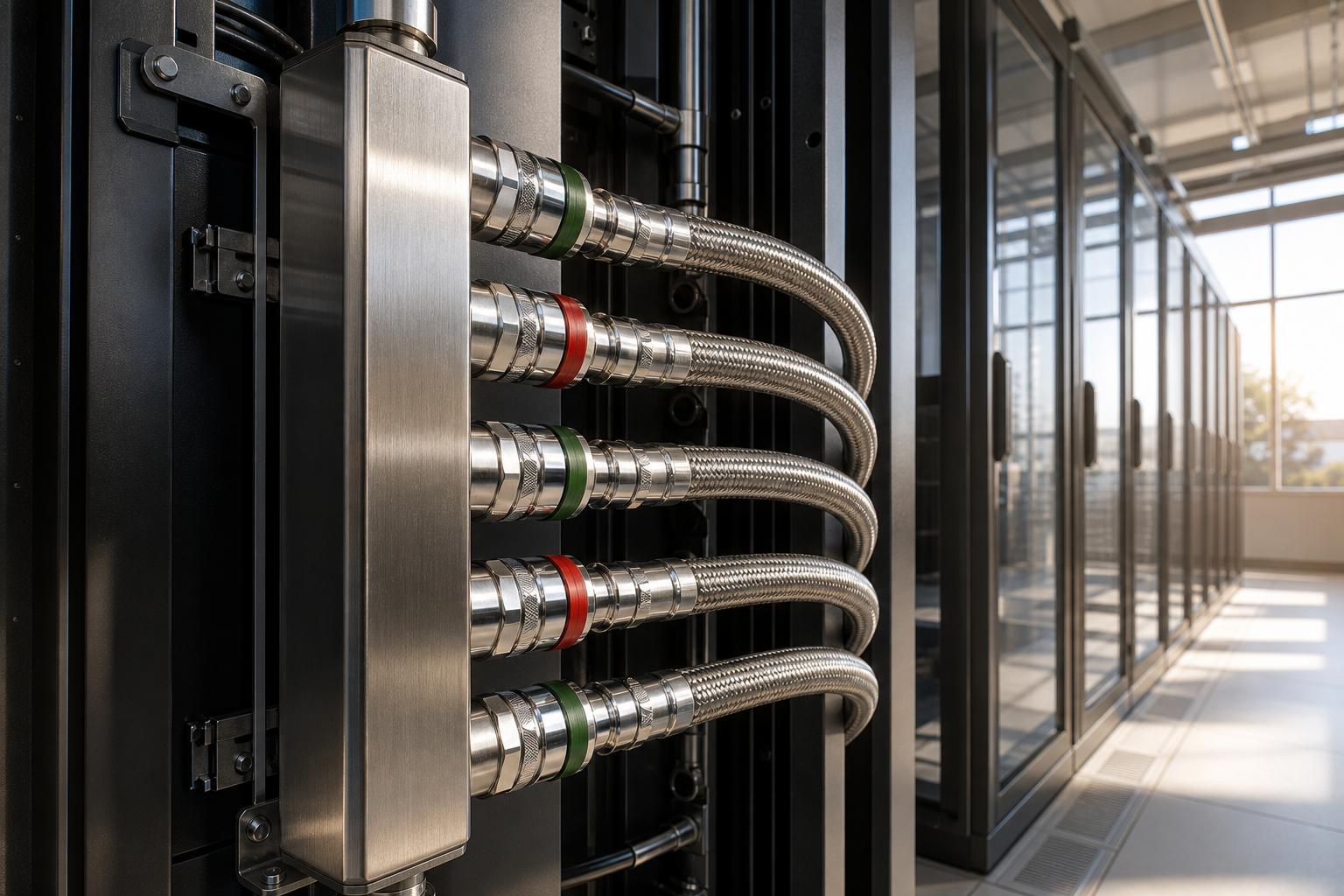
Direct-to-chip liquid cooling (DLC) circulates coolant through cold plates mounted directly on the GPU, CPU, and other high-heat-flux components, removing heat at the source rather than relying on air to carry it away. Equinix describes DLC as operating through four interconnected layers, facility-level coolant distribution, the CDU, rack-level cooling and control, and leak detection and containment, and notes that DLC "has emerged as the dominant approach for supporting high-density AI infrastructure" [4]. Facility-level coolant distribution consists of a primary loop from the building chiller to the CDU and a separate secondary loop from the CDU to the servers, which never mix fluids and instead exchange heat through a plate heat exchanger, while the CDU itself transfers cooling power to the servers and returns captured heat to the building system; CDUs are typically built with N+1 redundant pumps, redundant power connections, and, at the facility level, redundant units altogether.
Chilldyne's published design assumptions for a hypothetical 500 kW rack illustrate the flow-rate engineering involved: a 9 kW server node requires a coolant flow rate of roughly 13 liters per minute (lpm), with coolant entering at 40°C and exiting at 50°C, a 10°C temperature rise, and a cold-plate pressure drop of 1.8 pounds per square inch (psi) [18]. At the rack level, a manifold handling the full 500 kW load must carry roughly 600 lpm (158 gallons per minute), typically through a 3-inch square stainless-steel tube [18]. Two-phase direct liquid cooling, which uses engineered fluorinated fluids rather than water, trades flow-rate simplicity for handling complexity: Chilldyne's comparison found that two-phase cooling requires roughly five times less coolant flow on the inlet side but "40x more than water cooling" on the vapor-return side [18], and it recommends pipe diameters of four inches or smaller for practical liquid cooling installations, since larger vapor-return lines "will be hard to handle in the IT deployment phase" [18]. Dell'Oro's market analysis confirms that single-phase direct liquid cooling, which keeps coolant entirely in liquid form throughout the loop, accounts for the vast majority of liquid-cooled capacity coming online today, while two-phase DLC remains largely confined to pilots and early large-scale deployments as chip-level heat flux increases [6].
Rear-door heat exchangers (RDHx) offer a less invasive alternative or complement to DLC. An RDHx replaces the standard rear door of a server rack with a finned heat exchanger through which facility chilled water or a dedicated coolant loop circulates; server fans pull air through the servers and then through the exchanger, removing heat before it enters the room. Commercial units such as Motivair's ChilledDoor advertise cooling capacity up to 75 kW per rack with "100% heat removal and maintain room-neutral cooling," meaning the rack contributes essentially no net heat to the surrounding data hall [23]. RDHx units require no floor modifications and minimal plumbing, and industry retrofit estimates put installed costs around $8,000 to $15,000 per rack for 15 to 30 kW of capacity, while comparable in-row cooling units cost $20,000 to $35,000 and support 40 to 100 kW, making both common bridge technologies for facilities not ready for full DLC [15]. Digital Realty combines both approaches in its high-density colocation offering, noting that "the combination of RDHx with DLC effectively doubles the power densities that can be supported," enabling management of 30 to 150 kW per rack and beyond [24].
Immersion cooling, the third architecture, submerges entire servers directly in a dielectric fluid, either single-phase (fluid stays liquid) or two-phase (fluid boils at the chip surface and condenses at the tank lid) [5]. Microsoft's two-year, peer-reviewed life-cycle assessment, published in Nature, evaluated air cooling, cold plates, single-phase immersion, and two-phase immersion for general compute chips and found that cold plates and both immersion methods reduce greenhouse gas emissions by 15 to 21%, energy use by 15 to 20%, and water usage by 31 to 52% relative to air cooling over their full life cycles [13]. The study flagged an important caveat: two-phase immersion cooling, while performing best across most measured categories, "currently relies on liquid polyfluoroalkyl (PFAS) substances, which are facing increasing regulatory pressure in both the European Union and the United States" [13]. Notably, Microsoft's own researchers concluded cold plates alone can match immersion cooling's benefits: "It was interesting to see that cold plates could be as good as the two immersion cooling methods" [13], a finding that helps explain why cold-plate DLC, rather than immersion, has become the default architecture for GPU clusters. TechTarget's engineering guidance also cautions that immersion servicing is more involved than air- or DLC-based maintenance, since a technician replacing a component "must be lifted out of the dielectric liquid, no small task in itself, and the fluid cleaned off the components" before work can begin [5].
Meta has taken a related but distinct approach, closing the loop entirely at the facility level: its AI-optimized data centers use "a direct-to-chip liquid, closed-loop cooling system, with the typical design using dry coolers," meaning heat is rejected to ambient air through finned dry coolers rather than evaporative cooling towers [12]. Because the loop never evaporates water for cooling, Meta reports "no operational water use in the cooling system, and water use at the site is minimal and limited to domestic and janitorial needs, equipment cleaning and fire protection" [12]. This dry-cooler approach trades some energy efficiency, since it forgoes the free-cooling benefits of evaporative heat rejection, for a substantial reduction in water risk, a tradeoff that is becoming increasingly common as data center water use draws regulatory and community scrutiny.
Chiller Plant and Heat Rejection Design
Whatever combination of air and liquid cooling a facility deploys at the rack, that heat ultimately has to be rejected outside the building, and the central plant responsible for this is the chiller plant. A chiller removes heat from one medium, typically water or a water-glycol mix, and transfers it to another, usually outside air or a cooling tower loop, which is then rejected to the atmosphere. Chiller plants can be air-cooled, rejecting heat directly to ambient air through condenser coils, or water-cooled, rejecting heat to a separate condenser water loop that runs through an evaporative cooling tower. The choice carries a direct efficiency-versus-water tradeoff: Equinix notes that a facility using air cooling exclusively "would typically report a water usage effectiveness (WUE) of 0," while one using evaporative cooling exclusively "could report a WUE as high as 2.5," with WUE measured in cubic meters of water per megawatt-hour of energy consumed [25].
Free cooling, also called economization, is the single largest efficiency lever available to a chiller plant. An air-side economizer brings outside air directly into the data hall when ambient conditions are cool and dry enough, bypassing mechanical refrigeration entirely; a water-side economizer achieves the same result at the chilled-water loop, using a cooling tower to chill water without running the compressor [1]. Both approaches are sometimes described as offering redundancy value, since they can maintain partial cooling if mechanical systems go offline. Google popularized chiller-less, air-side-economized design as early as 2008 with a Belgium facility cooled entirely by outside air [1], and Microsoft's own 300,000-square-foot Dublin facility, opened in 2009, "uses only air-side economizers for cooling" and allows server inlet temperatures as high as 95°F [1]. NetApp's Global Dynamic Laboratory, the first data center to earn the ENERGY STAR label, uses free cooling for more than 75% of the year and partial free cooling more than 98% of the time, cutting building costs by more than 66% and operating costs by roughly 60% [1]. Intel demonstrated free cooling was feasible even at high densities, running a data center at up to 43 kW per rack and a facility-wide 1,100 watts per square foot with server inlet temperatures set to 95°F, achieving free cooling for all but 39 hours in an entire year and a resulting PUE of just 1.07 [1]. A separate 10-month Intel study of outside-air cooling found humidity varied from 4% to over 90% and changed rapidly at times, yet "no increase in server failure was observed" [1].
Free cooling is not without tradeoffs. Introducing outside air raises particulate and humidity control concerns, and retrofitting an existing facility for air-side economization is often impractical: Oracle reportedly abandoned an economizer retrofit because its raised-floor, downflow-cooled design had no convenient path to bring in large volumes of outdoor air, and because of humidity and contamination concerns [1]. A 2013 retrofit at Marvell Semiconductor's Santa Clara headquarters, adding an air-side economizer to a 5,000-square-foot, 720 kW data center served by three chillers rated 340, 340, and 310 tons, cost $662,000 and saved roughly $27,000 per month, paying back in 2.0 years without utility incentives and 1.5 years with them [1]. Separate research from Pacific Gas and Electric and Lawrence Berkeley National Laboratory found that data centers using air-side economizers had higher particle concentrations than those using minimal outside air, though improved filter design can mitigate the difference [1].
For GPU-dense facilities using liquid cooling, chiller plant design also has to account for the higher facility water supply temperatures that direct-to-chip loops can tolerate, since warmer coolant loops enable more hours of free cooling. ASHRAE's liquid cooling classes formalize this: Class W17/W27 describes facilities "traditionally cooled using chillers and a cooling tower, but with an optional water-side economizer to improve energy efficiency, depending on the location of the data center," supplying water at 17°C or 27°C [10]; Class W32/W40 describes facilities typically operated without chillers in most locations, though some may still require them [10]; and Class W45/W+ describes facilities "typically operated without chillers to take advantage of energy efficiency and reduce capital expense," supplying water at 45°C or higher, though "some locations may not be suitable for drycoolers" at that class [10]. Designing a GPU data center's chiller plant, in other words, increasingly means designing for the highest facility water supply temperature the chip vendor's cold plates will tolerate, since every degree of headroom converts directly into hours of chiller-free operation and lower energy cost per rack.
Calculating Cooling Capacity and Designing for Redundancy
Sizing a cooling system correctly starts with quantifying the total heat load, and the calculation begins from the same principle used throughout this report: electrical power consumed by IT equipment is, for almost all practical purposes, equal to the heat that equipment produces. Heat output has historically been expressed in several units, including British thermal units (BTU) per hour, tons of refrigeration, and watts, and converting between them is a routine part of cooling design:
- To convert BTU per hour to watts, multiply by 0.293, and to convert tons of refrigeration to watts, multiply by 3,530 [26].
- To convert watts to BTU per hour, multiply by 3.41, and to convert watts to tons of refrigeration, multiply by 0.000283 [26].
Total facility cooling load is the sum of several components, not just IT equipment power. Design guidance recommends summing the load power of all IT equipment, then adding the heat contribution of uninterruptible power supply (UPS) systems using the formula (0.04 x power system rating) + (0.05 x total IT load power), power distribution systems using (0.01 x power system rating) + (0.02 x total IT load power), lighting at roughly 2.0 watts per square foot, and personnel at approximately 100 watts per person at maximum occupancy [26]. Humidity control adds further headroom in large facilities with significant air mixing, and once all sources are tallied, designers typically add up to 30% of oversizing for dehumidification effects and size total cooling capacity to roughly 1.3 times the expected IT load before adding redundant capacity [26].
Redundancy is the final, and arguably most consequential, design variable, since cooling failures are a leading cause of serious outages. Vertiv's engineering guidance frames redundancy using an N-based notation, where N represents the baseline number of cooling units, such as chillers or CDUs, required to meet full thermal load with zero spare capacity, and N+1 redundancy adds one extra unit beyond that baseline, so that if a chiller needing four units to run at full load instead has five installed, any single unit can fail or be pulled for maintenance without loss of cooling; Vertiv describes this level as "the industry-standard minimum for cooling system design in modern data centers" [3]. Higher-availability designs escalate from there: N+2 tolerates two simultaneous failures and suits research clusters with high uptime needs but cost sensitivity; 2N fully duplicates the entire cooling system, including separate power and cooling paths, so an entire system can fail without disruption, and is typical of national labs and Tier IV-grade facilities; and 2N+1 adds a spare component on top of full duplication for cloud-scale AI clusters that cannot tolerate any cooling interruption [3].
Cooling redundancy design is often mapped directly onto the Uptime Institute's four-level Tier Classification system for data center availability. Tier I facilities offer basic capacity, where "site-wide shutdowns are required for maintenance or repair work" and any capacity or distribution failure impacts the site [27]. Tier III facilities are "concurrently maintainable," meaning "each and every capacity component and distribution path in a site can be removed on a planned basis for maintenance or replacement without impacting operations," a description that maps closely onto N+1 cooling redundancy [27]. Tier IV facilities are fully "fault tolerant," such that "an individual equipment failure or distribution path interruption will not impact operations," the standard most closely associated with 2N cooling architectures [27]. Uptime Institute has issued more than 4,000 Tier Certification awards across more than 122 countries, making it the most widely referenced third-party validation of both power and cooling design in the industry [27].
Table 1 below summarizes the ASHRAE thermal envelopes that govern air-cooled and liquid-cooled data center design, drawn from the 2021 fifth-edition Thermal Guidelines for Data Processing Environments.
| ASHRAE Class | Cooling Medium | Recommended / Design Condition | Typical Application |
|---|---|---|---|
| A1 to A4 | Air | 18°C to 27°C recommended; A2 allows 10°C to 35°C, A3 allows 5°C to 40°C, and A4 allows 5°C to 45°C | General-purpose enterprise servers, storage, and networking [26] |
| H1 | Air (high-density) | 18°C to 22°C recommended; 15°C to 25°C allowable | Tightly integrated, high-power server and accelerator systems that lack room for larger heat sinks [16] |
| W17/W27 | Liquid | Facility water supply at 17°C or 27°C | Chiller/cooling-tower plants, optionally with a water-side economizer [10] |
| W32/W40 | Liquid | Facility water supply at 32°C or 40°C | Cooling-tower-fed loops typically run without chillers in most climates [10] |
| W45/W+ | Liquid | Facility water supply at 45°C or higher | Chiller-less, dry-cooler heat rejection for maximum capital and energy efficiency [10] |
As the table shows, the newer liquid-cooling classes are designed explicitly to push facility water temperatures upward, since a GPU rack cooled by a W45-class loop can reject heat through simple dry coolers rather than mechanical chillers for most of the year, a direct efficiency and capital-cost benefit unavailable to air-cooled A1 through A4 facilities. Data center designers increasingly negotiate with GPU vendors over the maximum coolant supply temperature their cold plates can tolerate specifically because every additional degree of tolerance shifts a facility toward a higher, cheaper-to-operate ASHRAE liquid class.
Data Analysis and Evidence
The quantitative picture of GPU data center cooling in 2026 is one of rapid technology transition set against a slow-moving base of existing infrastructure. On the market side, Dell'Oro Group's Data Center Liquid Cooling Advanced Research Report found the liquid cooling market is expected to roughly double in 2025 to reach close to $3 billion in manufacturer revenue, continuing to scale toward approximately $7 billion by 2029 [6]. The firm identifies Vertiv as the market leader in liquid cooling, with CoolIT, nVent, and Boyd holding strong positions and Aaon delivering rapid growth on the back of deep hyperscaler partnerships [6]. Hyperscalers account for a substantial share of that revenue, with the remainder concentrated in colocation facilities purpose-built for AI workloads [6].
On the efficiency side, the industry's headline metric remains stubbornly flat even as leading operators pull far ahead of the mean. Uptime Institute's 2025 Global Data Center Survey, based on responses from operators worldwide, found that "average PUE levels show little change for the sixth consecutive year, with improvements constrained by legacy infrastructure and region-specific barriers to efficient cooling" [7]. The same survey found that "impactful data center outages are gradually becoming less frequent," a reassuring signal even as absolute rack counts and densities climb across the industry [7]. Facilities commissioned within the last five years fare somewhat better, averaging a PUE of 1.48, and those larger than 20 MW average around 1.44, with newer high-latitude facilities in North America and Europe reaching 1.3 or better [8]. Google's fleet, by contrast, reports a 2025 average PUE of 1.09, described as using 83% less overhead energy than the industry average, a figure Google calculates directly against Uptime's own 1.54 industry benchmark (Source: datacenters.google).
On the water side, Google reports that in 2025, 87% of its freshwater withdrawal came from sources with low or medium risk of water depletion or scarcity, and the company signed agreements for more than 12 gigawatts (GW) of net-new clean energy that year to support its data center growth (Source: datacenters.google). Water usage effectiveness varies enormously by cooling architecture: Equinix notes that an all-air-cooled facility reports a WUE near zero, while an all-evaporative facility can report a WUE as high as 2.5 cubic meters per megawatt-hour, and most real facilities land somewhere in between depending on how much of the year they run in economizer mode versus evaporative mode [25].
Retrofit economics are a growing part of the picture as operators weigh new construction against upgrading existing facilities. Industry analysis compiled by data center services firm Introl, citing 451 Research, estimates that retrofitting a legacy facility with liquid cooling can achieve roughly 70% of new-construction performance at about 20% of the cost [15]. That same analysis found that 68% of enterprise data centers built before 2015 lack the power density and cooling capacity for modern AI workloads, even though 82% of those facilities have ten or more years remaining on their leases, a mismatch that is driving much of the current retrofit demand rather than pure new-build activity [15].
Table 2 below compares the primary GPU data center cooling technologies discussed in this report across density, water use, and typical deployment context.
| Technology | Typical Density Range | Water Use | Typical Use Case |
|---|---|---|---|
| CRAC (DX refrigerant) | Below 200 kW per room/zone | None to low (varies by condenser type) | Small and low-density facilities, edge sites [20] |
| CRAH (chilled water) | 200 kW and above per room/zone | Moderate (tied to chiller plant) | Mid-to-large facilities prioritizing efficiency [20] |
| Rear-door heat exchanger | Up to 75 kW per rack | Moderate (facility chilled water) | Retrofit bridge technology, mixed air/liquid halls [23] |
| Direct-to-chip liquid cooling | 120 kW to 500 kW+ per rack | Low to moderate (dry cooler or tower dependent) | GPU training and inference clusters [24] |
| Immersion cooling | Variable, tank-limited | Low (closed dielectric loop) | Dense HPC and edge deployments, selective adoption [6] |
The pattern that emerges from Table 2 is a rough correlation between density and liquid content: as racks move from tens of kilowatts toward hundreds, the cooling medium shifts from air, to chilled water at the rack door, to liquid delivered directly to the chip. No single technology dominates every use case, and most large GPU facilities in 2026 deploy a hybrid stack, direct-to-chip cooling for GPUs and high-power accelerators, rear-door heat exchangers or conventional CRAH for storage, networking, and CPU racks, and a chiller or dry-cooler plant sized to the blended load of both.
Case Studies and Real-World Examples
NVIDIA and Vertiv: The GB200 NVL72 Reference Architecture
NVIDIA's contribution of its GB200 NVL72 rack and tray designs to the Open Compute Project (OCP) in 2024 illustrates how GPU vendors are now co-designing cooling infrastructure rather than treating it as a downstream integration problem. The GB200 NVL72 rack integrates 36 Grace CPUs and 72 Blackwell GPUs into a single NVLink domain requiring 120 kW of cooling capacity, addressed through "an enhanced Blind Mate Liquid Cooling Manifold design" and a "Floating Blind Mate Tray connection" that distributes coolant to both compute and switch trays [2]. NVIDIA partnered with Vertiv to create a joint reference architecture that can reduce implementation time for data centers deploying the platform by up to 50%, and more than 40 data center infrastructure providers, including Vertiv, CoolIT, Boyd, Motivair, Nvent, and Schneider Electric, are now building on top of the resulting open reference designs, which together enable operators to "deploy 7MW GB200 NVL72 clusters globally" using pre-engineered power and cooling designs rather than building each element from scratch [2]. This case demonstrates a broader industry shift: GPU cooling design is increasingly standardized at the silicon vendor level rather than left to individual data center operators to solve independently.
xAI Colossus: Building a 100,000-GPU Liquid-Cooled Cluster in Memphis
xAI's Colossus supercomputer, built in a converted factory outside Memphis, Tennessee, is one of the most heavily documented large-scale GPU liquid cooling deployments to date. According to a Supermicro-sponsored technical tour, the cluster's initial build of 100,000 NVIDIA H100 GPUs was completed in just 122 days [11]. The basic building block is a Supermicro liquid-cooled rack comprising eight 4U servers, each with eight H100 GPUs, for a total of 64 GPUs per rack, cooled by an in-rack coolant distribution unit with redundant pumps and hot-swappable power supplies [11]. Rather than relying solely on direct-to-chip cooling, Colossus pairs cold plates with rear-door heat exchangers, since "each rack needs to be cooling neutral to the data hall to avoid installing massive air handlers" [11]. Notably, the facility also pairs its electrical infrastructure with on-site Tesla Megapack battery storage to buffer the millisecond-scale power swings that large AI training jobs create as workloads shift between GPUs, a reliability measure closely tied to thermal stability since sudden power spikes can strain cooling response times [11].
Meta: Closed-Loop, Water-Free Direct-to-Chip Cooling at Hyperscale
Meta's next-generation AI data center design illustrates an operator prioritizing water risk mitigation over the marginal efficiency gains of evaporative cooling. Its facilities use a direct-to-chip, closed-loop liquid cooling system paired with dry coolers rather than cooling towers, which Meta states results in "no operational water use in the cooling system" at all [12]. Water consumption at these sites is limited strictly to domestic plumbing, janitorial needs, equipment cleaning, and fire protection systems, a sharp contrast to the evaporative cooling towers that remain common at many hyperscale campuses [12]. This design choice reflects a broader tension the industry is navigating between PUE optimization, which historically favored evaporative cooling, and water stewardship commitments in regions facing scarcity concerns, a tradeoff explored in the WUE-versus-PUE discussion earlier in this report.
Microsoft: Peer-Reviewed Life-Cycle Evidence for Liquid Cooling
Microsoft's two-year life-cycle assessment study, published in the peer-reviewed journal Nature and led by Husam Alissa, director of systems technology in cloud operations and innovation at Microsoft, provides some of the most rigorous independent evidence available on the environmental tradeoffs between cooling architectures [13]. The study evaluated air cooling, cold plates, single-phase immersion, and two-phase immersion across their full supply chain and eventual disposal, finding the three liquid options each reduce emissions, energy, and water use relative to air cooling, while also quantifying that switching from a typical grid to 100% renewable energy could cut greenhouse gas emissions by 85 to 90% regardless of which cooling technology is used [13]. Despite exploring immersion cooling extensively, the company had not, as of the study's publication, deployed immersion systems in its production data center operations, instead favoring cold plate DLC [13]. Co-author Teresa Nick, Microsoft's director of natural systems and sustainability, framed the goal as informing engineering tradeoffs early: "In a nutshell, we're trying to understand the trade-offs. You're trying to understand the context of what you're doing and what the impacts are" [13].
Digital Realty and Lenovo: High-Density Colocation for a Financial Services Client
Digital Realty's May 2024 launch of advanced liquid-to-chip cooling support, available across more than half of the company's data centers globally, gives a concrete colocation example of retrofit-style deployment at scale [24]. A European financial services company with tens of millions of clients worldwide used the offering, paired with Lenovo Neptune direct liquid cooling, to scale high-performance computing capacity for financial risk calculations [14]. Digital Realty's high-density colocation, combined with interconnection on its PlatformDIGITAL platform, allowed the client to deploy six times faster than a comparable build-out would have taken, while Lenovo Neptune direct liquid cooling improved the client's energy efficiency by 30% [14]. IDC Research Director Sean Graham described the underlying offering as aligning "with IDC's colocation provider recommendations for the gen AI market," underscoring how third-party analysts now expect colocation providers to offer liquid cooling as a baseline capability rather than a premium add-on [24].
Implications and Future Directions
The trajectory of GPU data center cooling design points toward three converging trends over the remainder of the decade. First, liquid cooling will become the default, not the exception, for any facility hosting frontier AI accelerators. With chip TDPs projected to exceed 4,000 W by 2029 and racks already reaching 200 kW with a trend line toward 1 MW, as established earlier, air alone will not be a viable primary cooling medium for leading-edge GPU clusters within the next several product generations [6]. Facility water supply temperature will likely keep rising in tandem, as designers push toward ASHRAE's W40 and W45 liquid classes specifically to unlock more hours of chiller-less, dry-cooler-only operation [10].
Second, the industry faces a widening bifurcation between purpose-built AI facilities and the legacy data center stock. The majority of existing enterprise facilities were designed for 3 to 7 kW racks with raised floors rated for 150 pounds per square foot, structurally incapable of hosting a 3,000-pound liquid-cooled GPU rack without reinforcement, as discussed above. With most pre-2015 enterprise facilities lacking adequate density and cooling capacity for modern AI workloads, and the majority of those facilities carrying a decade or more of remaining lease term, operators face a genuine strategic choice between costly retrofit and abandoning otherwise serviceable real estate. Given that retrofits can reportedly reach roughly 70% of new-construction performance at around 20% of the capital cost, expect retrofit activity, rather than purely greenfield construction, to account for a growing share of new liquid-cooled capacity, particularly among enterprises and smaller colocation operators who cannot match hyperscaler capital budgets, as detailed in the data analysis above.
Third, reliability engineering around cooling will intensify as densities rise. With cooling already responsible for a meaningful share of serious data center outages, as established earlier, the historical practice of treating cooling redundancy as a secondary concern behind electrical redundancy is likely to erode. N+1 CDU and chiller redundancy, already described as the industry-standard minimum, is likely to give way to 2N and 2N+1 architectures for the largest cloud-scale AI clusters as the cost of a thermal excursion, which can force GPU throttling or shutdown mid-training-run, grows relative to the incremental cost of redundant cooling hardware.
On water, the tension between PUE optimization and water stewardship that Meta's dry-cooler design and Equinix's WUE analysis both illustrate is likely to sharpen as regulators in water-stressed regions impose tighter withdrawal limits. Equinix's own caution, that "regulations that set aggressive WUE targets without linking those targets to PUE and local environmental conditions may have unintended effects," pushing operators back toward more energy-intensive air cooling, suggests that future policy design will need to weigh water and energy metrics jointly rather than in isolation [25]. Finally, expect continued standardization efforts, following NVIDIA's OCP contribution and the ASHRAE W-class liquid cooling framework, aimed at reducing the current fragmentation across CDU, manifold, and quick-disconnect designs, since interoperability directly determines how quickly an operator can source components during a capacity crunch. TechTarget's engineering analysis frames the stakes plainly: "given the increasing pressure to support greater sustainability, liquid cooling could become the only viable option, so organizations should prepare for the transition" [5].
Frequently Asked Questions (FAQs)
What is the difference between CRAC and CRAH cooling in a data center? A CRAC (computer room air conditioner) uses a self-contained direct-expansion refrigerant cycle, while a CRAH (computer room air handler) cools air using chilled water supplied by a separate central chiller plant; CRAC units suit facilities under roughly 200 kW of electrical load, and CRAH units generally suit larger facilities above that threshold [20].
Is liquid cooling always better than air cooling for GPU racks? Not universally, but at GPU densities above roughly 20 to 30 kW per rack, liquid cooling becomes a practical necessity rather than an optimization, since air alone cannot move enough heat without excessive fan power and airflow volume; Dell'Oro Group characterizes liquid cooling as now "a functional requirement for large-scale AI deployments" rather than an efficiency upgrade [6].
How wide should a cold aisle be in a hot aisle/cold aisle containment design? The ANSI/TIA-942 standard recommends a cold aisle width of approximately 1.2 meters, or 4 feet, to optimize cooling efficiency and equipment access [9].
How do I calculate the cooling capacity a data center needs? Sum the load power of all IT equipment (which equals its heat output), add UPS and power distribution system losses using ASHRAE-aligned formulas, add lighting and personnel heat, then apply an oversizing factor for humidity control and redundancy; a common rule of thumb sizes total cooling capacity at roughly 1.3 times expected IT load before redundancy, before layering on N+1 or higher redundancy for the mechanical plant itself.
What cooling capacity does a single GPU rack like the NVIDIA GB200 NVL72 require? The GB200 NVL72 requires 120 kW of cooling capacity per rack, addressed through direct liquid cooling manifolds and quick-disconnect couplings rather than air cooling, and the successor GB300 NVL72 can reportedly exceed that figure in production, as noted in the executive summary above.
Can an existing data center be retrofitted for liquid cooling, or does it require new construction? Retrofits are common and, according to industry analysis, can achieve roughly 70% of new-construction thermal performance at around 20% of the capital cost, though structural constraints such as raised-floor loading and ceiling height can make some legacy facilities unsuitable regardless of budget, as detailed in the data analysis above.
What data center Tier level is required to support high-density GPU cooling reliably? There is no fixed requirement, but Tier III facilities, which are "concurrently maintainable" and allow any cooling component to be serviced without impacting operations, are generally treated as the practical minimum for production AI clusters, while the largest cloud-scale deployments increasingly target Tier IV-equivalent, fully fault-tolerant 2N cooling architectures [27].
Conclusion
GPU data center cooling design has moved from a supporting engineering function to a first-order strategic decision that determines whether an organization can deploy modern AI accelerator hardware at all. The technical toolkit spans a wide range, from conventional CRAC and CRAH air conditioning through hot aisle and cold aisle containment, to direct-to-chip liquid cooling, rear-door heat exchangers, immersion cooling, and the chiller and economizer plants that ultimately reject captured heat to the environment. Each technology occupies a specific density and cost niche, and most GPU-dense facilities now deploy several of them together rather than relying on any single approach.
The evidence gathered in this report points to a consistent conclusion: air cooling remains adequate for general enterprise workloads but is structurally unable to serve GPU racks drawing 120 kW or more, which is why liquid cooling adoption is accelerating industry-wide even as the broader data center fleet's efficiency metrics, including PUE, remain largely unchanged. Rigorous airflow management and containment discipline, standards-based thermal envelopes from ASHRAE, careful capacity calculation, and redundancy planning proportional to workload criticality, mapped onto recognized Tier classifications, together determine whether a GPU data center operates reliably or becomes another statistic in the growing share of outages attributed to cooling failure. Organizations planning new AI infrastructure, or evaluating whether to retrofit existing facilities, should treat cooling architecture as a decision made in parallel with, not subordinate to, compute procurement, since the design choices covered in this report, from CDU redundancy to facility water temperature class, will determine both the reliability and the total cost of ownership of GPU infrastructure for years after it is commissioned.
External Sources (27)
About
GPUSmith
Plan and build private AI compute with GPU Smith. We connect workload requirements with GPU hardware, networking, deployment and operating decisions so your infrastructure fits the work it must perform.
GPU Smith provides independent engineering and research for private AI infrastructure. We help technical buyers and operators reason about GPU workload sizing, hardware selection, procurement, deployment and inference operations, from the compute system to the networking, power and cooling requirements around it.
Start with the workload
Useful infrastructure decisions begin with the models, data, throughput, latency and operating constraints a team actually has. GPU Smith helps connect those requirements with system design and deployment choices. The goal is a privately controlled AI environment whose capacity and operational demands are understood before a purchasing decision.
Hardware and supplier research
Our public reference library covers GPUs, complete systems and networking components. The server-vendor directory and manufacturing research help teams investigate suppliers, compare options and follow sources behind technical claims. We distinguish manufacturer specifications from measured benchmarks and advertised capabilities from tested configurations. Reference pages are research resources, not a live inventory listing or a binding equipment quote.
Deployment and operations
GPU Smith's engineering scope includes infrastructure integration, networking, power, cooling and the practical operation of inference workloads. Our published articles explain the tradeoffs behind deployment, procurement and ongoing operations so teams can ask better questions and document decisions.
Work with GPU Smith
Explore the hardware library, GPU references, networking references and vendor research. Contact GPU Smith with your workloads and deployment constraints to discuss a project and confirm current scope, pricing and availability.
Inclusion of a manufacturer or product in our research does not imply a partnership, certification or endorsement.
Disclaimer
This document is provided for informational purposes only. No representations or warranties are made regarding the accuracy, completeness, or reliability of its contents. Any use of this information is at your own risk. GPUSmith shall not be liable for any damages arising from the use of this document. This content was generated with assistance from artificial intelligence tools, which may contain errors or inaccuracies. Readers should verify critical information independently. All product names, trademarks, and registered trademarks mentioned are property of their respective owners and are used for identification purposes only. Use of these names does not imply endorsement. This document does not constitute professional or legal advice. For specific guidance related to your needs, please consult qualified professionals.