GPUSmith Article
CDU Sizing for GPU Racks: Flow per kW, Delta-T, Coolant
Size a CDU for liquid-cooled GPU racks: L/min per kW for water and PG25, approach temperature, pressure drop, N+1 pumps, and what GB200/GB300 data exists.
Summary
- 01Size the CDU for heat that actually goes to liquid, using the rack vendor's flow requirements and metered rack power rather than nameplate power.
- 02Compare CDU capacities at the same approach temperature, coolant, temperature rise and external pressure. The headline capacity can fall substantially at a tighter approach.
- 03A larger temperature rise reduces flow and pump energy, but the rack vendor's supply and return limits set the allowable range. Warmer supply can raise flow and pressure drop.
- 04Choose coolant against the server vendor's warranty and wetted-materials list, then size flow and pressure using that fluid's actual concentration and temperature.
- 05Define redundancy at the pump, CDU or loop level. Check the entire secondary circuit at design flow, including the loaded filter condition.
Inside this article
- 01Two loops, three temperatures
- 02Heat balance: Q = m × cp × ΔT
- 03What CDU datasheets show: L/min per kW vs approach
- 04Delta-T trade-offs
- 05Coolant choice: PG25 vs water vs DI
- 06Facility water: W-classes and 45 °C warm water
- 07Rack-scale numbers: what is and isn't published
- 08CDU types and topology
- 09Redundancy, pressure drop and filtration
- 10Sizing worked example: eight NVL72-class racks
- 11What to ask a CDU vendor
- 12FAQ
- 13Commissioning handoff
- 14Sources
Two loops, three temperatures
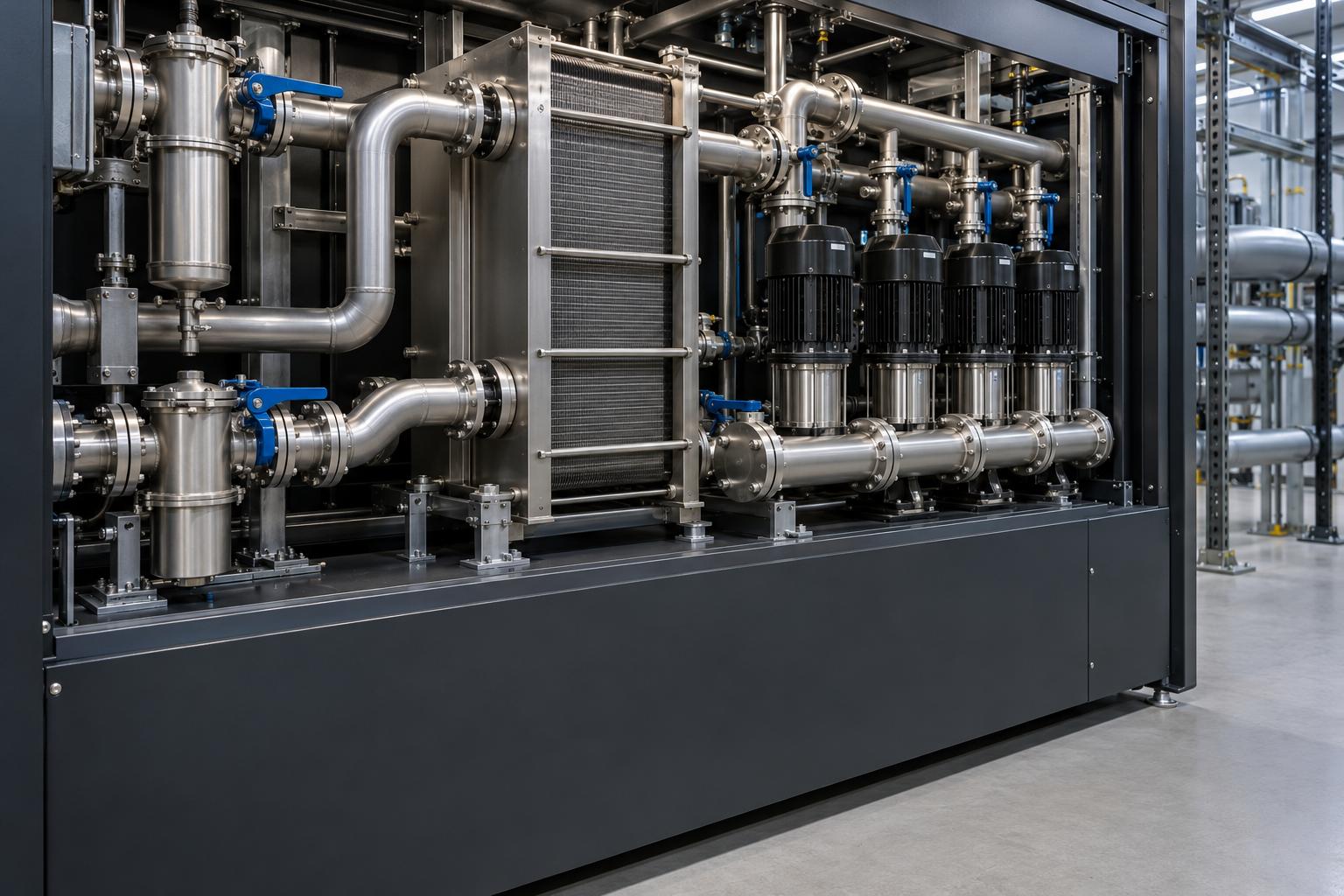
A coolant distribution unit (CDU) is a heat exchanger with pumps, filters and controls. It sits between two separate liquid circuits. The facility water system (FWS) is the building side: cooling towers, dry coolers or chillers, and the pipes that run to the CDU. The technology cooling system (TCS) is the closed secondary loop. It runs from the CDU through rack manifolds, hoses, quick disconnects and cold plates, then back. ASHRAE TC 9.9 notes that a CDU lets the TCS run a coolant other than facility water, hold its supply above room dew point, and keep chemistry separate from the FWS. It also states that "the requirements for the TCS loop are more stringent than for the FWS loop" [1]. ASHRAE classifies the facility side with "W" classes and the CDU-to-IT piping with "S" classes. The S class should be coordinated with the IT manufacturer [2].
Every CDU selection comes down to three temperatures:
- FWS entering temperature: the facility water reaching the CDU's primary side.
- TCS supply temperature: the coolant the CDU delivers to the racks. The IT vendor specifies this.
- TCS return temperature: the supply temperature plus the temperature rise across the racks.
The approach temperature is the gap between TCS supply and FWS entering temperature. A 4 °C approach means 26 °C facility water can produce 30 °C coolant for the racks [3]. ASHRAE's datacom chapter puts the burden on the designer: "It is incumbent on the facility owner/designer to ensure the approach temperature for any planned CDU is taken into account" [4].
The wider facility picture is in GPU data center cooling design; this article covers flow, temperature rise and CDU capacity.
Heat balance: Q = m × cp × ΔT
The sizing equation is the steady-state energy balance:
P = ρ × V̇ × cp × ΔT
- P is the heat carried by the liquid (kW).
- ρ is coolant density (kg/L).
- V̇ is volumetric flow (L/s).
- cp is specific heat (kJ/kg·K).
- ΔT is the rise from supply to return (K).
Rearranged into the unit facilities engineers ask for:
L/min per kW = 60 / (ρ × cp × ΔT)
Property values used here
| Fluid | Density | Specific heat | ρ × cp | Basis |
|---|---|---|---|---|
| Water | 994.03 kg/m³ at 35 °C | 4.1796 kJ/kg·K at 40 °C | 4.15 kJ/L·K | Engineering ToolBox density, specific heat |
| PG25 (assumed 25 % by mass) | ~1,007 kg/m³ at 40 °C | ~3.97 kJ/kg·K | ~3.99 kJ/L·K | Interpolated from Engineering ToolBox 20 % and 30 % rows |
For propylene glycol, Engineering ToolBox lists specific heat of 0.960 and 0.935 Btu/lb·°F for 20 % and 30 % solutions by mass. It lists density of 1,004 and 1,010 kg/m³ at 40 °C. The 25 % values in the table above are our linear interpolation of those rows. Treat them as assumptions: commercial "PG25" is often specified by volume, and inhibitor packages shift properties slightly. Use the coolant maker's datasheet at your actual concentration and temperature for final design.
Flow per kW at several temperature rises (derived)
| ΔT across rack | Water (L/min per kW) | PG25 (L/min per kW) |
|---|---|---|
| 5 K | 2.89 | 3.00 |
| 8 K | 1.81 | 1.88 |
| 10 K | 1.44 | 1.50 |
| 12 K | 1.20 | 1.25 |
| 15 K | 0.96 | 1.00 |
Arithmetic for one cell: 60 / (3.99 × 10) = 1.50 L/min per kW for PG25 at a 10 K rise. Halving ΔT doubles the flow, and PG25 needs about 4 % more flow than water; its viscosity effect on pressure drop matters more.
Apply P to the heat that actually goes to liquid, not to nameplate power. ASHRAE's handbook says plainly that "a nameplate rating does not represent actual power draw during usage" [4]. Rack power estimation is covered in GPU rack power planning.
What CDU datasheets show: L/min per kW vs approach
Vendor datasheets confirm the arithmetic and add the variable the equation leaves out: approach temperature. Delta's GoCool-1500 liquid-to-liquid CDU publishes four operating points [5]:
| Capacity | Approach | Secondary flow | Primary flow | L/min per kW | Implied TCS ΔT with PG25 (derived) |
|---|---|---|---|---|---|
| 1,500 kW | 6 °C | 1,500 LPM | 1,300 LPM | 1.0 | ~15.0 K |
| 1,375 kW | 6 °C | 1,650 LPM | 1,300 LPM | 1.2 | ~12.5 K |
| 1,250 kW | 5 °C | 1,500 LPM | 1,300 LPM | 1.2 | ~12.5 K |
| 1,016 kW | 4 °C | 1,524 LPM | 1,300 LPM | 1.5 | ~10.0 K |
The same page specifies:
- Secondary loop: PG25, 331 kPa external pressure drop, 50 µm filter (upgradeable to 25 µm).
- Primary loop: water at 17 °C inlet, 114 kPa pressure drop, 500 µm filter.
- Pumps: 3+1 (N+1) or 4 pumps in N mode.
The implied ΔT column is our derivation, not a Delta figure. The headline 1,500 kW assumes a 6 °C approach and roughly a 15 K rise; at a 4 °C approach the same frame is rated at 1,016 kW, about a third less.
Vertiv's Liebert XDU1350 shows the same effect. It is rated 1,368 kW nominal at a 4 °C approach and 2,912 kW maximum at an 8 °C approach. Its maximum flow is 1,200 l/m at 2.44 bar external differential pressure with one pump running, and 1,800 l/m at 1.98 bar with two [6]. Vendor capacities are only comparable at the same approach, ΔT, fluid and external pressure. Addendum b to ASHRAE Standard 127-2020, approved by ASHRAE and ANSI on 2026-02-27, now fixes the full-load test point for liquid-to-liquid CDUs [7]:
- 26 °C FWS entering
- 30 °C TCS leaving
- 4 °C approach
- 39.6 °C TCS return at 100 % load
- Water on the FWS side and 25 % propylene glycol on the TCS side
That 9.6 K rise works out to about 1.56 L/min per kW of PG25 (derived). Ask vendors for a 127 Addendum b rating. Schneider Electric warns that a CDU is set up "according to the vendor's instructions" for rating tests [3]. If the filter is removed, the published external pressure looks better than what you will get in service.
These datasheets are illustrations, not NVIDIA validation.
Delta-T trade-offs
A larger ΔT means less flow, smaller pipes and lower pump energy, but warmer coolant at the downstream end of each cold plate. ΔT is bounded by the IT vendor's supply and return limits, not by the CDU.
The clearest public example of this coupling is Lenovo's GB300 NVL72 System Configuration Guide (First Edition, April 2026). It gives required rack flow and rack pressure drop for each fluid supply temperature [8]:
| Supply temperature | Required rack flow | Rack pressure drop |
|---|---|---|
| 25 °C | 59 LPM | 2.3 psi |
| 30 °C | 71 LPM | 3.2 psi |
| 35 °C | 89 LPM | 4.9 psi |
| 40 °C | 119 LPM | 8.5 psi |
| 45 °C | 177 LPM | 18.4 psi |
Lenovo does not state the rack heat load or coolant behind this table, but one pattern stands out. Flow × (55 − supply temperature) is nearly constant: 1,770, 1,775, 1,780, 1,785 and 1,770 L/min·K for the five rows. That is what you would expect if the rack is designed around a return temperature of about 55 °C. Each step up in supply temperature then shrinks the allowable ΔT, from about 30 K at 25 °C to about 10 K at 45 °C.
If that reading is right, 1,775 L/min·K corresponds to roughly 118 kW (PG25) to 123 kW (water) of heat into the liquid. This is our inference from the published numbers, not a Lenovo specification.
The table also shows the hydraulic cost of warm water. Tripling the flow from 59 to 177 LPM raises the rack pressure drop eightfold, from 2.3 to 18.4 psi (about 16 to 127 kPa). That is consistent with pressure drop scaling roughly with the square of flow (derived exponent ≈ 1.9).
Coolant choice: PG25 vs water vs DI
| Factor | Treated water / DI | PG25 |
|---|---|---|
| ρ × cp (derived above) | ~4.15 kJ/L·K | ~3.99 kJ/L·K |
| Freeze protection | None | 20 % by mass freezes at −8 °C, 30 % at −14 °C [9] |
| Viscosity / pressure drop | Lower | Higher; use the CDU and cold-plate vendor's PG curves |
| Biological and corrosion control | Inhibitor and biocide programme | Inhibited glycol package; still needs monitoring |
PG25 has become the default reference fluid on the TCS side. The ASHRAE 127 Addendum b rating conditions use it, and Delta's datasheet specifies it. Lenovo's GB300 guide lists non-operating storage limits for both "Di-H20" and PG25 [8].
The choice is usually set by the server vendor's warranty and wetted-materials list, not by the CDU. ASHRAE notes that TCS fluid chemistry "is often proprietary in nature as selected/designed by the IT manufacturer." It also requires every wetted part on each side of the CDU to be chemically compatible with that side's fluid [1]. Size flow and pressure with the fluid you will actually fill. A CDU curve plotted for water will overstate available head on glycol.
- Lower viscosity and pressure drop than PG25.
- Requires an inhibitor and biocide programme.
- Needs about 4 % more flow than water; viscosity has a larger effect on pressure drop.
- Uses an inhibited glycol package and still needs monitoring.
The choice is usually set by the server vendor's warranty and wetted-materials list, not by the CDU. Size flow and pressure with the fluid you will actually fill. A CDU curve plotted for water will overstate available head on glycol.
Vendor capacities are only comparable at the same approach, ΔT, fluid and external pressure.
Facility water: W-classes and 45 °C warm water
ASHRAE's fifth edition thermal guidelines renamed the facility-water classes by their upper supply limit: W17, W27, W32, a new W40, W45, and W+ for above 45 °C. The older W1–W5 classes had a 2 °C lower bound. Compliance requires "full, unthrottled operation of the ITE at all temperatures within the respective W-class" [10].
For CDU sizing, the class sets the warmest FWS you must still handle. Add the CDU approach to get the warmest TCS supply. Then check that against the rack's flow table.
At CES in January 2026, NVIDIA said Vera Rubin can be cooled with 45 °C water "with no chillers necessary" [11]. Read that next to the Lenovo GB300 table. Warm water removes chillers, but at the warm end flow per rack rises about threefold and pressure drop about eightfold, and the approach temperature eats directly into the margin. Liquid-to-air units make this worse: ASHRAE notes that "liquid/air heat exchangers have much higher approach temperatures than liquid/liquid" [12].
Rack-scale numbers: what is and isn't published
As of 2026-10-28, NVIDIA publishes no per-rack coolant flow or supply temperature for GB200 NVL72 or GB300 NVL72; the product pages say only "a rack-scale, liquid-cooled design" and a "fully liquid-cooled, rack-scale architecture" (GB200 NVL72, GB300 NVL72). NVIDIA gives a GB200 rack power figure but none for GB300. The figures that are public:
| Source | Published figure | What it is |
|---|---|---|
| NVIDIA DGX GB200 user guide | "The rack power consumption is approximately 120kW"; eight power shelves with 33 kW input each, N+N; compute trays liquid-cooled, networking and storage air-cooled [13] | Rack power, no flow or temperature |
| NVIDIA DGX SuperPOD GB200 reference architecture | "Each SU requires a Thermal Design Power (TDP) of 1.2 Megawatts (MW)"; an SU is 8 DGX GB200 rack systems; hybrid liquid plus air cooling [14] | SU-level power, not per-rack flow |
| Supermicro SRS-GB200-NVL72 | 8× 33 kW power shelves, "total power 132kW"; in-rack 250 kW CDU with dual hot-swap pumps; 1.3 MW in-row CDU option; 180/240 kW liquid-to-air option [15] | Power-shelf capacity and CDU options, no flow |
| Vertiv reference design 020 (6× GB200 SuperPODs) | 130 kW compute racks; 72 % liquid and 28 % air per pod; 2× XDU1350 per pod, N+1 [16] | One vendor's facility design |
| Lenovo GB300 NVL72 | 59–177 LPM per rack at 25–45 °C supply (table above) | OEM rack flow requirement |
| NVIDIA DGX B300 | "15 kW system max." (14.5 kW consumption), 10U (DGX B300 user guide; product page rounds to "~14 kW") | System power, no cooling data |
Blog posts quoting a single "GB200 rack flow" disagree widely; we used none of them. Ask the OEM, in writing, for the flow table matching your SKU, fluid and supply temperature.
CDU types and topology
- In-rack CDU (for example Supermicro's 250 kW unit): the failure domain is one rack, and no TCS piping runs across the hall. It takes rack space and puts pumps in every rack.
- In-row or floor-standing liquid-to-liquid (the Delta and Vertiv units above, 1–1.4 MW class): one unit feeds a row through secondary piping. Fewer pumps, larger failure domain. Delta lists the GoCool-1500 at 1,900 kg with coolant on a 1,200 × 1,200 mm footprint, which belongs in the floor loading worksheet.
- Liquid-to-air (sidecar or in-rack): rejects TCS heat into room air where no facility water exists. The approach is worse and the heat still has to leave the room by air.
On one 2+ MW CDU vs several smaller units: one large unit with N+1 pumps still has a single heat exchanger, controller and header. Several units at unit-level N+1, as in Vertiv's 2× 1,368 kW per pod, survive losing a whole CDU, at the cost of floor space and TCS valving.
Redundancy, pressure drop and filtration
Pumps and power. Delta offers 3+1 pumps, dual power feed and redundant control sensors. Vertiv's XDU1350 runs dual pump (N+1) or triple pump (N) modes. Decide whether redundancy is required at the pump, the CDU or the loop, and size flow at the N condition.
Pressure. The CDU's available external pressure must cover the whole TCS at design flow: piping, valves, manifolds, hoses, quick disconnects, cold plates and sensors. "The sum of all these pressure drops represents the TCS's total pressure drop," and it rises with flow [3]. ASHRAE says manufacturers "typically provide configuration-specific flow rate and pressure differential requirements" [4]. Collect them for every component.
Filtration. ASHRAE TC 9.9 recommends a TCS filter with an absolute rating "7 to 10 times smaller than the finest channel dimension in the IT cooling equipment." It also says design flow and pressure drop should be taken at the loaded ("dirty") filter state [1]. Schneider Electric's article attributes a looser rule to ASHRAE: no larger than half the smallest micro-channel dimension. The two ratios differ, so use the cold-plate vendor's filter requirement. Typical CDU filters are 50 µm, upgradeable to 25 µm (Delta), or 50 µm (Vertiv).
Sizing worked example: eight NVL72-class racks
Illustrative inputs, labelled as such because NVIDIA publishes no per-rack liquid load:
- 8 compute racks at 130 kW IT each (Vertiv's figure, slightly above NVIDIA's ~120 kW DGX GB200 rack power), with 80 % going to liquid. This mirrors the Vertiv reference design: 832 kW liquid out of 1,040 kW of compute racks per pod (derived from its 1,152 kW pod, 72 % liquid, and 8 × 14 kW networking racks).
- PG25 on the TCS, design ΔT 10 K, so 1.50 L/min per kW.
Step 1, liquid load. 8 × 130 × 0.80 = 832 kW.
Step 2, TCS flow. 832 × 1.50 = 1,248 L/min, or about 156 L/min per rack.
Step 3, CDU at the approach you can afford. With 26 °C facility water and a required 30 °C TCS supply, the approach is 4 °C. Delta's 4 °C point is 1,016 kW at 1,524 LPM, which leaves about 18 % heat margin and 22 % flow margin. Vertiv's XDU1350 nominal 1,368 kW at a 4 °C approach leaves more. For N+1 at the CDU level, use two units, each able to carry the full 832 kW.
Step 4, conservative case. Now assume all 132 kW of power-shelf capacity goes to liquid. That gives 1,056 kW and 1,584 L/min at a 10 K rise. Both exceed Delta's 4 °C point. Either widen ΔT to 12 K (1,320 L/min), accept a 5 °C approach (1,250 kW rating), or add CDU capacity.
Step 5, facility side. Delta's 1,300 LPM of 17 °C primary water carrying 1,500 kW implies a primary rise of about 16.6 K (derived). Check that the plant can supply that flow at that temperature in the warmest hour of the W-class.
Replace every input with OEM data and metered rack power before purchase.
- 01Calculate liquid load
Assume eight racks at 130 kW each, with 80 % going to liquid: 832 kW.
- 02Calculate secondary flow
At 1.50 L/min per kW for PG25 and a 10 K rise, the example needs 1,248 L/min, about 156 L/min per rack.
- 03Select at the required approach
With 26 °C facility water and 30 °C rack supply, select at a 4 °C approach. The Delta point leaves about 18 % heat margin and 22 % flow margin.
- 04Check the conservative case
Putting all 132 kW per rack into liquid gives 1,056 kW and 1,584 L/min. Widen the temperature rise, accept a larger approach or add CDU capacity.
- 05Check the facility side
Confirm the plant can supply the required primary flow and temperature in the warmest hour of the facility water class.
Replace every input with OEM data and metered rack power before purchase.
What to ask a CDU vendor
- Rated capacity at your FWS temperature, approach, TCS ΔT and fluid concentration, not the headline point.
- Pump curve showing external pressure available at design flow, with the filter installed and at the loaded-filter condition.
- Redundancy mode (N+1 pumps, dual feed, sensor redundancy) and capacity at N.
- Filter rating (absolute vs nominal) and hot-swap method.
- Wetted materials list checked against the server vendor's list.
- Controls: supply-temperature or differential-pressure control, BMS protocols, leak and dew-point inputs.
- Factory acceptance test at your conditions. Schneider notes published ratings "rarely match application ratings."
- Evidence of qualification with your rack OEM. A CDU datasheet is not NVIDIA or OEM validation.
FAQ
Which CDU vendors publish validated flow specs for 120 kW Blackwell racks? As of 2026-10-28 we found no public NVIDIA-validated per-rack flow specification for GB200 or GB300; NVIDIA's own GB200 figure is rack power (~120 kW), not flow. Lenovo publishes a GB300 rack flow table. CDU vendors such as Delta and Vertiv publish generic capacity, flow and approach points. Supermicro lists CDU options without flow.
Commissioning handoff
The numbers chosen here become acceptance criteria: design flow, ΔT, approach, external pressure and filter pressure drop at each CDU and rack. The cold plate commissioning checklist covers how to prove them in the field with a staged-load heat balance. For an independent review of a CDU selection against your rack OEM's data, see GPU Smith.
Sources
- GoCool-1500 Liquid-to-Liquid Coolant Distribution Unit specifications — Delta Electronics, accessed 2026-10-28
- Liebert XDU450/1350 Coolant Distribution Units brochure — Vertiv, accessed 2026-10-28
- Vertiv AI reference design 020: 6x 1.2MW NVIDIA DGX SuperPODs (GB200 NVL72) — Vertiv, 2024, accessed 2026-10-28
- Account for filtering too! Beware of how CDU rating capacity is specified — Schneider Electric, 2025-12-16, accessed 2026-10-28
- Water-Cooled Servers: Common Designs, Components, and Processes — ASHRAE TC 9.9, 2019, accessed 2026-10-28
- Emergence and Expansion of Liquid Cooling in Mainstream Data Centers — ASHRAE TC 9.9, 2021, accessed 2026-10-28
- ASHRAE Handbook, Chapter 20: Data Centers and Telecommunication Facilities — ASHRAE, accessed 2026-10-28
- Designing for AI Workloads — ASME, May 2026, accessed 2026-10-28
- Major Changes to ASHRAE's Fifth Edition of Thermal Guidelines, Part 3: Liquid Cooling Chapter Updates — Upsite Technologies, 2024-07-31, accessed 2026-10-28
- Vera Rubin hot water cooling reveal triggers HVAC share drop — DatacenterDynamics, 2026-01-07, accessed 2026-10-28
- Lenovo NVIDIA GB300 NVL72 System Configuration Guide (Machine Type 7DJV) — Lenovo, First Edition April 2026, accessed 2026-10-28
- NVIDIA GB200 NVL72 — NVIDIA, accessed 2026-10-28
- NVIDIA GB300 NVL72 — NVIDIA, accessed 2026-10-28
- NVIDIA DGX GB200 User Guide: Hardware — NVIDIA, updated 2026-09-17, accessed 2026-10-28
- ANSI/ASHRAE Addendum b to Standard 127-2020 — ASHRAE, approved 2026-02-27, accessed 2026-10-28
- DGX SuperPOD Architecture (GB200 reference architecture) — NVIDIA, updated 2025-11-19, accessed 2026-10-28
- NVIDIA DGX B300 — NVIDIA, accessed 2026-10-28
- SuperServer SRS-GB200-NVL72 — Supermicro, accessed 2026-10-28
- Water: Specific Heat vs. Temperature — Engineering ToolBox, accessed 2026-10-28
- Water: Density, Specific Weight and Thermal Expansion Coefficients — Engineering ToolBox, accessed 2026-10-28
- Propylene Glycol based Heat-Transfer Fluids — Engineering ToolBox, accessed 2026-10-28
External Sources (16)
About
GPUSmith
Plan and build private AI compute with GPU Smith. We connect workload requirements with GPU hardware, networking, deployment and operating decisions so your infrastructure fits the work it must perform.
GPU Smith provides independent engineering and research for private AI infrastructure. We help technical buyers and operators reason about GPU workload sizing, hardware selection, procurement, deployment and inference operations, from the compute system to the networking, power and cooling requirements around it.
Start with the workload
Useful infrastructure decisions begin with the models, data, throughput, latency and operating constraints a team actually has. GPU Smith helps connect those requirements with system design and deployment choices. The goal is a privately controlled AI environment whose capacity and operational demands are understood before a purchasing decision.
Hardware and supplier research
Our public reference library covers GPUs, complete systems and networking components. The server-vendor directory and manufacturing research help teams investigate suppliers, compare options and follow sources behind technical claims. We distinguish manufacturer specifications from measured benchmarks and advertised capabilities from tested configurations. Reference pages are research resources, not a live inventory listing or a binding equipment quote.
Deployment and operations
GPU Smith's engineering scope includes infrastructure integration, networking, power, cooling and the practical operation of inference workloads. Our published articles explain the tradeoffs behind deployment, procurement and ongoing operations so teams can ask better questions and document decisions.
Work with GPU Smith
Explore the hardware library, GPU references, networking references and vendor research. Contact GPU Smith with your workloads and deployment constraints to discuss a project and confirm current scope, pricing and availability.
Inclusion of a manufacturer or product in our research does not imply a partnership, certification or endorsement.
Disclaimer
This document is provided for informational purposes only. No representations or warranties are made regarding the accuracy, completeness, or reliability of its contents. Any use of this information is at your own risk. GPUSmith shall not be liable for any damages arising from the use of this document. This content was generated with assistance from artificial intelligence tools, which may contain errors or inaccuracies. Readers should verify critical information independently. All product names, trademarks, and registered trademarks mentioned are property of their respective owners and are used for identification purposes only. Use of these names does not imply endorsement. This document does not constitute professional or legal advice. For specific guidance related to your needs, please consult qualified professionals.